Tripping type lightning protection piezoresistor
A technology of varistors and conductive rods, which is applied in the direction of resistors, resistor parts, non-adjustable metal resistors, etc., can solve the problems that the circuit cannot be disconnected in time without varistor cooling, and the varistor is inconvenient to disassemble. Overhaul and replacement, effects of preventing burning
- Summary
- Abstract
- Description
- Claims
- Application Information
AI Technical Summary
Problems solved by technology
Method used
Image

Examples
Embodiment 1
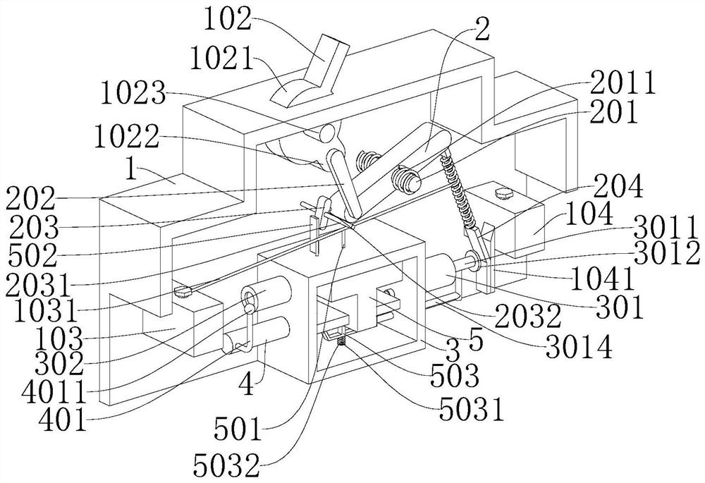
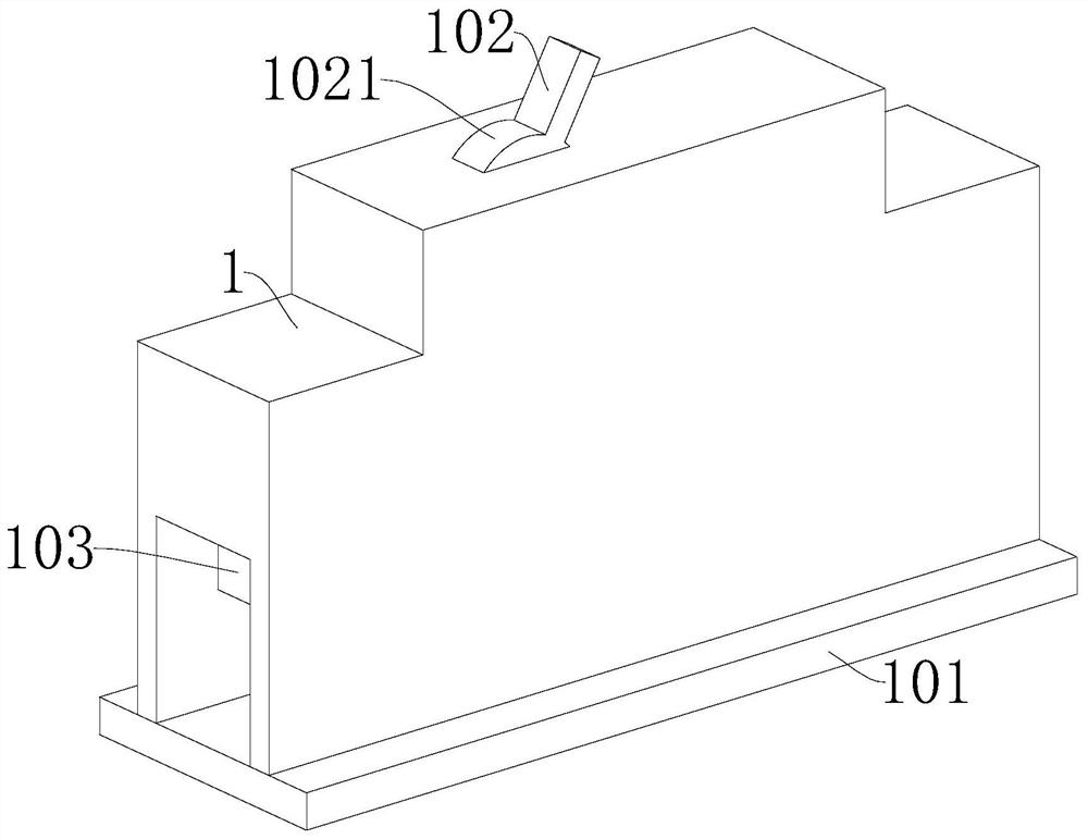
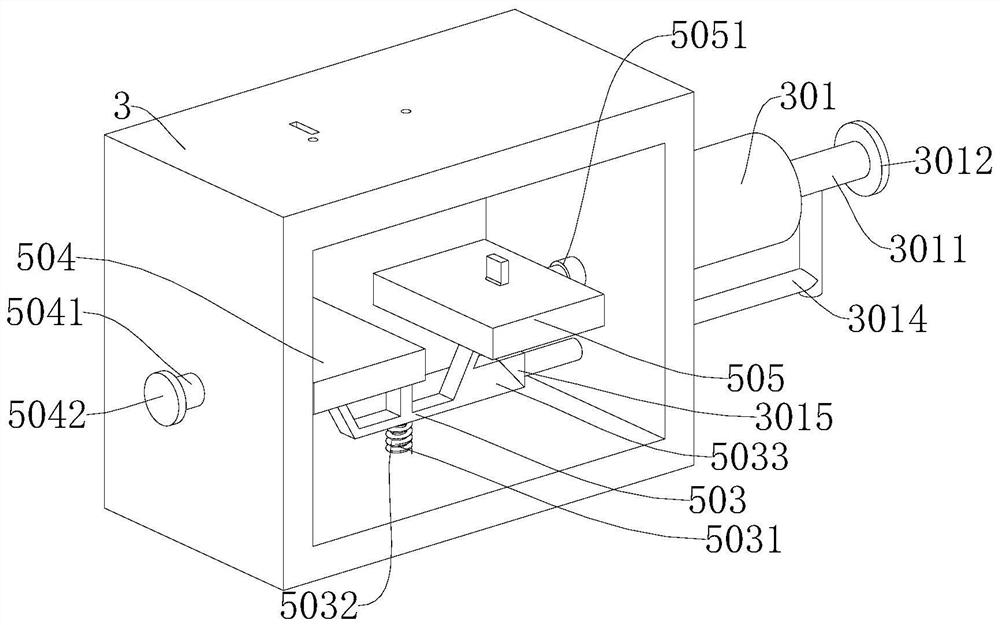
[0028] refer to Figure 1-5 , a varistor for tripping type lightning protection, comprising a mounting case 1, a first support rod 1023 is fixedly connected to the mounting case 1, a ring 1021 is rotatably connected to the first support rod 1023, and a ring 1021 is fixedly connected to the first support rod 1023 There is a shift lever 102, a first junction block 103 and a second junction block 104 are fixedly connected in the installation shell 1, a conductive sheet 1041 is fixedly connected on the second junction block 104, a cutting mechanism is provided on the ring 1021, and a cutting mechanism is provided on the cutting mechanism. There is a first cooling mechanism, an unlocking mechanism is provided on the first cooling mechanism, a second cooling mechanism is arranged on the unlocking mechanism, and a bottom plate 101 is disassembled and connected to the bottom of the installation shell 1 .
[0029] When the circuit is struck by lightning or the voltage is too high, the tem
Embodiment 2
[0039] refer to Figure 1-5 , is basically the same as Embodiment 1, furthermore, the cutting mechanism includes a rotating rod 2, a second rod 201 is fixedly connected in the installation shell 1, and the rotating rod 2 is connected to the second rod 201 in rotation, and the second rod 201 is sleeved with a torsion spring 2011, and the two ends of the torsion spring 2011 are fixedly connected to the installation shell 1 and the rotating rod 2 respectively, one end of the rotating rod 2 is connected to the connecting rod 202 in rotation, and the ring 1021 is fixedly connected to the connecting ring 1022 One end of the connecting rod 202 away from the rotating rod 2 is rotatably connected to the connecting ring 1022, the other end of the rotating rod 2 is fixedly connected with a conductive rod 204, the conductive rod 204 is attached to the conductive sheet 1041, and the first terminal block 103 is fixedly connected with a Copper wire 1031, the end of copper wire 1031 far away fro
PUM
 Abstract
Description
Claims
Application Information
 - R&D Engineer
- R&D Manager
- IP Professional
- Industry Leading Data Capabilities
- Powerful AI technology
- Patent DNA Extraction
Browse by: Latest US Patents, China's latest patents, Technical Efficacy Thesaurus, Application Domain, Technology Topic.
© 2024 PatSnap. All rights reserved.Legal|Privacy policy|Modern Slavery Act Transparency Statement|Sitemap