Circuit for diverting surges and transient impulses

a technology of transient impulses and circuits, applied in the direction of overvoltage protection resistors, emergency protective arrangements for limiting excess voltage/current, coupling device connections, etc., can solve the problem of inability to divert the leading portion of the surge, severe damage to electronic equipment, and extremely susceptible to damage and destruction of electronic equipment. the effect of reducing the let-through voltage and energy, reducing the size, and prolonging the bandwidth

Inactive Publication Date: 2005-11-24
INFINITE ELECTRONICS INT INC
View PDF18 Cites 12 Cited by
  • Summary
  • Abstract
  • Description
  • Claims
  • Application Information

AI Technical Summary

Benefits of technology

The technical effect of this patented technology is that it provides an improved way to suppress electrical shocks caused by sudden changes in power supply. This means that even if there are slight differences between different types of power supplies or devices, they can still work properly with each other without causing damage.

Problems solved by technology

This patent describes a problem with traditional surge suppressors that use gas tubing to provide protection against electrical shocks due to lightning strikes. These devices cannot switch overvoltage events effectively without causing damage.

Method used


Image

  • Circuit for diverting surges and transient impulses
  • Circuit for diverting surges and transient impulses

Examples


Embodiment Construction

[0015] A circuit that implements the various features of the present invention will now be described with reference to the drawings. The drawings and the associated descriptions are provided to illustrate embodiments of the present invention and not to limit the scope of the present invention. Reference in the specification to “one embodiment” or “an embodiment” is intended to indicate that a particular feature, structure, or characteristic described in connection with the embodiment is included in at least an embodiment of the invention. The appearances of the phrase “in one embodiment” in various places in the specification are not necessarily all referring to the same embodiment. Throughout the drawings, reference numbers are re-used to indicate correspondence between referenced elements. In addition, the first digit of each reference number indicates the figure in which the element first appears.

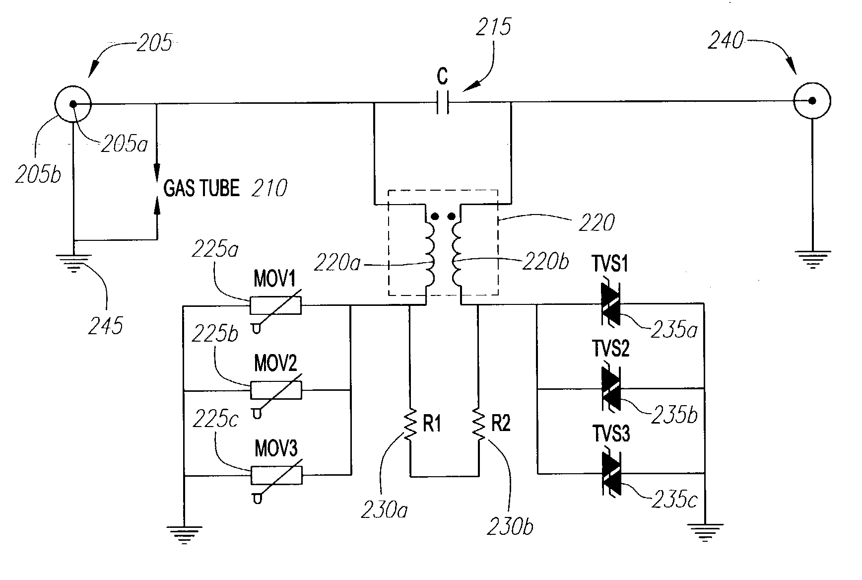
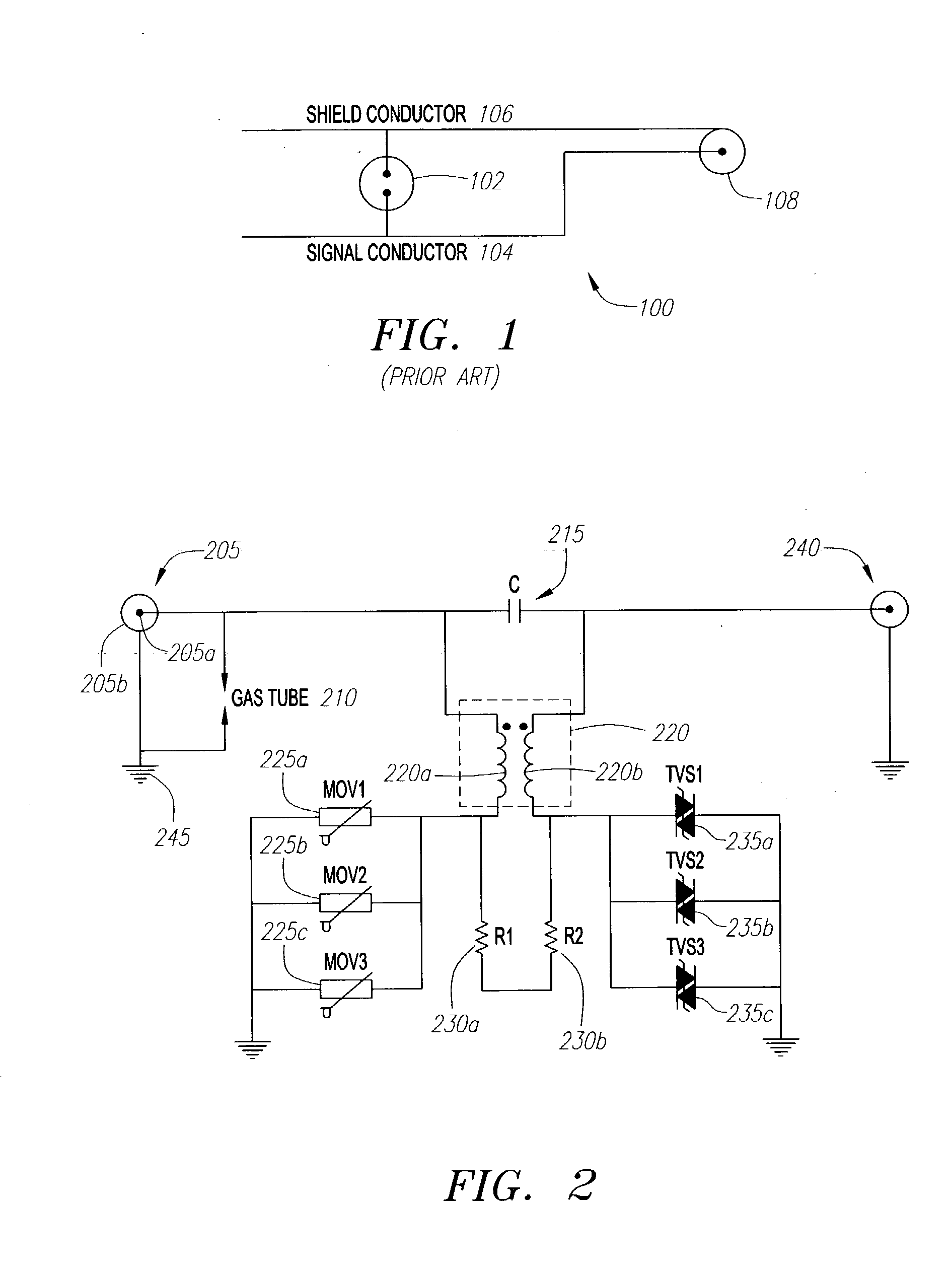
[0016] Referring now more particularly to the drawings, FIG. 2 is a schematic diagram


PUM


Abstract

A circuit for attenuating a surge is disclosed that might include a conductor for receiving the surge, a capacitor, positioned along the conductor, for blocking the surge, and a gas tube having a first end coupled to the conductor and a second end coupled to a ground. The circuit might also include a transformer having a first wire and a second wire, the transformer being coupled to the conductor, a resistor coupled to the first and second wires of the transformer, a varistor coupled to the first wire of the transformer, and a diode coupled to the second wire of the transformer.

Description


Claims


Application Information

Patent Timeline
Owner INFINITE ELECTRONICS INT INC
Why Eureka
Try Eureka