Real-time monitoring unmanned aerial vehicle control panel

A control panel and real-time monitoring technology, applied in non-electric variable control, control/adjustment system, three-dimensional position/channel control, etc., can solve the problems of inaccurate signal receiver detection information, inability to observe and record, and poor functionality. Achieve the effect of improving accuracy and safety, improving functionality and convenience, and improving practicability

Inactive Publication Date: 2018-03-13
NANJING HANXIYUE AUTOMATION TECH CO LTD
View PDF0 Cites 2 Cited by
  • Summary
  • Abstract
  • Description
  • Claims
  • Application Information

AI Technical Summary

Benefits of technology

This patented technology allows for better monitoring over long periods without having to constantly check or change equipment settings. There's no physical connection needed like traditional methods that require constant attention from human operators. Instead, this system uses sensors placed inside the aircraft itself instead of relying solely upon visual inspections alone. Its main technical effect is improved efficiency and security during surveillance operations while maintaining ease of use.

Problems solved by technology

Technological Problem: Current Real Time Monitoring (RTM) Controller Plane Interface (CPUI), which uses cameras with adjustors to monitor objects like firearms during flight, requires precise positional knowledge from pilots beforehand. Additionally, current Remote Unmanned Surveillance Platform (RUSPWS) controls panels lack accuracy due to their limited function and difficulty observing ground features such as distance between them.

Method used


Image

  • Real-time monitoring unmanned aerial vehicle control panel
  • Real-time monitoring unmanned aerial vehicle control panel
  • Real-time monitoring unmanned aerial vehicle control panel

Examples


Embodiment Construction

[0019] The following will clearly and completely describe the technical solutions in the embodiments of the present invention with reference to the accompanying drawings in the embodiments of the present invention. Obviously, the described embodiments are only some, not all, embodiments of the present invention. Based on the embodiments of the present invention, all other embodiments obtained by persons of ordinary skill in the art without making creative efforts belong to the protection scope of the present invention.

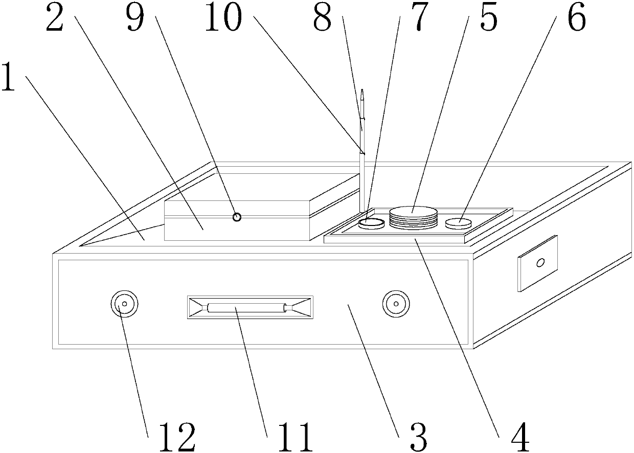
[0020] see Figure 1-2 , the present invention provides a technical solution: a real-time monitoring UAV control panel, including a device body 1, the inner wall of the front end of the device body 1 is provided with a built-in bin 3, and the built-in bin 3 is embedded in the device body 1, the front end of the built-in bin 3 is fixed with a buckle frame 12, the buckle frame 12 can conveniently pull and shrink the built-in bin 3, effectively improving the economy


PUM


Abstract

The invention discloses a real-time monitoring unmanned aerial vehicle control panel, comprising a device body, the inner wall of the front end of the device body is provided with a built-in bin, and the built-in bin is embedded in the inner side of the device body, the front end of the built-in bin A buckle frame is fixed, and a storage compartment is welded on the upper left side of the device body. A lock card is installed on the front end of the storage compartment, and the lock card is embedded in the outer wall of the storage compartment. There is a control panel on the right side, and a smart display is used, and the smart display is closely attached to the storage compartment. By observing the information received on the smart display with the naked eye, it is convenient to get a close-up view of the landforms in the distance. Observation and mapping, clearly presenting the photos taken by the drone on the screen, improving the functionality and convenience of the smart display, and easy to operate, will have a wide range of application market demands in the future.

Description


Claims


Application Information

Patent Timeline
Owner NANJING HANXIYUE AUTOMATION TECH CO LTD
Why Eureka
Try Eureka