Vane-type pneumatic mineralizing equipment and pneumatic flotation cell using same

A mineralizer and blade-type technology, which is applied in the field of flotation separation process of coal selection, can solve the problems such as not suitable for metal mineral flotation, low kinetic energy conversion rate of ore pulp, difficult technology promotion, etc., and achieves easy operation. Control and control, reduce the amount of equipment maintenance, and improve the effect of mineralization

Pending Publication Date: 2018-04-06
ZHENGZHOU GOYOD RESOURCES NEW TECH CO LTD
View PDF12 Cites 4 Cited by
  • Summary
  • Abstract
  • Description
  • Claims
  • Application Information

AI Technical Summary

Benefits of technology

This patented technology improves efficiency by reducing energy usage while maintaining consistently high levels of cleanliness during flotations. It also reduces costs due to lower operating pressure requirements and simplifies the design of machinery used for this purpose. Additionally, there're no longer requiring electrical or fuel resources at all. Overall, these technical improvements help achieve better results over conventional systems.

Problems solved by technology

Inflator (Buff) Technological Model: A new type of fluidized bed reactor called BFC can be found at various locations around the country where gold production takes place. However, these devices require large amounts of electricity due to its design. Additionally, they generate significant noise during operations, leading to poor performance and reduced profit potential compared to other methods like cycling method. Therefore, finding ways to reduce electrical load while maintaining efficient gas flow remains challenges.

Method used


Image

  • Vane-type pneumatic mineralizing equipment and pneumatic flotation cell using same
  • Vane-type pneumatic mineralizing equipment and pneumatic flotation cell using same
  • Vane-type pneumatic mineralizing equipment and pneumatic flotation cell using same

Examples


Embodiment Construction

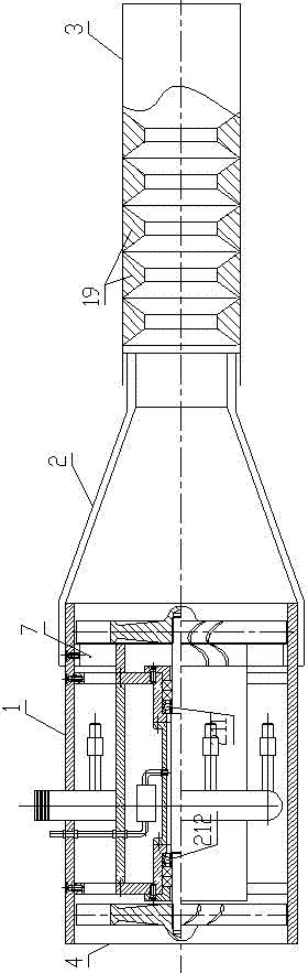
[0038] Such as Figure 1 to Figure 6 As shown, the vane-type pneumatic mineralizer of the present invention includes a cylindrical shell 1, with the pulp flow direction as the forward direction, the front and rear ends of the shell 1 are open, and the rear end of the shell 1 is opened as the pulp inlet. 4; The front end of the shell 1 is connected with a shrinking tube 2, the diameter of the shrinking tube 2 is larger at the rear and smaller at the front,

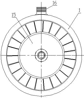
[0039] The housing 1 is provided with a central shaft 9, the front end of the central shaft 9 is connected with a power impeller 14, and the rear end of the central shaft 9 is connected with a slurry suction impeller 15; the power impeller 14 is located at the front end of the housing 1, and the slurry suction impeller 15 is located at the Rear end; the front end of central shaft 9 is equipped with front bearing 211, and front bearing 211 is supported by front bearing frame 81, and front bearing frame 81 is installed on the ho


PUM


Abstract

The invention discloses a vane-type pneumatic mineralizer, which comprises a cylindrical casing, the front and rear ends of the casing are open, and the rear opening of the casing is used as an ore slurry inlet; the front end of the casing is connected with a necking pipe, There is a central shaft inside the housing, and the front and rear ends of the central shaft are respectively connected with the power impeller and the suction impeller; the front end of the central shaft is equipped with a front bearing, and the rear end of the central shaft is equipped with a rear bearing, and the front and rear bearing frames are installed on the housing; There are several compressed air branch pipes at the casing, one end of the compressed air branch pipe is connected to the compressed air pipe, the other end of the compressed air branch pipe is located in the casing and behind the power impeller, the other end of the compressed air branch pipe is the compressed air outlet, and the compressed air outlet faces the power impeller. The invention has the advantages of static flotation, substantial energy saving, easy operation and control, strong equipment adaptability, easy transformation, greatly reduced construction costs, simplified maintenance, and long service life.

Description


Claims


Application Information

Patent Timeline
Owner ZHENGZHOU GOYOD RESOURCES NEW TECH CO LTD
Why Eureka
Try Eureka