Electronic chip welding device

A welding device, electronic chip technology, applied in auxiliary devices, welding equipment, printed circuits, etc., can solve the problems of different welding materials selection of different temperatures, unreasonable materials, low work efficiency, etc., to improve welding efficiency, Long service life and cost-saving effect

Inactive Publication Date: 2018-04-06
SICHUAN CHAOYING TECH CO LTD
View PDF0 Cites 4 Cited by
  • Summary
  • Abstract
  • Description
  • Claims
  • Application Information

AI Technical Summary

Problems solved by technology

In the existing device, the materials used for the soldering iron and the soldering iron core are unreasonable, and different temperatures cannot be selected corresponding to different soldering materials, resulting in high cost and low work efficiency.

Method used


Image

  • Electronic chip welding device
  • Electronic chip welding device
  • Electronic chip welding device

Examples


Example Embodiment

[0020] The present invention will be further explained below in conjunction with the drawings:

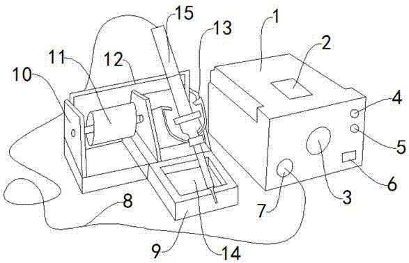
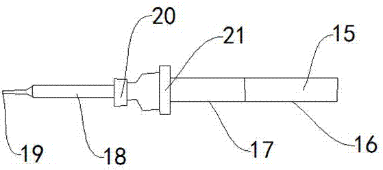
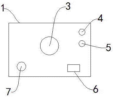
[0021] Such as Figure 1-Figure 3 As shown, an electronic chip soldering device includes a host 1, a tin wire 11, a soldering iron 15, a power lead 8, a high temperature resistant sponge 14, a soldering iron core 18, a soldering iron tip 19, and a clamp 20. The host 1 is provided with a host nameplate 2 There is a temperature adjustment knob 3 on the front of the host 1. The temperature adjustment knob 3 is used to adjust the temperature when welding different materials. One side of the temperature adjustment knob 3 is provided with a soldering iron socket 7, which is used to connect the power lead 8, and the temperature adjustment knob 3 There is a power indicator light 4 at the other end, a heating indicator light 5 is provided under the power indicator light 4, a switch button 6 is provided under the heating indicator light 5, a soldering iron base 9 is provided next to the host 1, an


PUM


Abstract

The invention discloses an electronic chip welding device, which comprises a host, tin wire, soldering iron, power leads, high temperature resistant sponge, soldering iron core, soldering iron head, clamp, the host nameplate is arranged on the host, and the front of the host is provided with Temperature adjustment knob, one side of the temperature adjustment knob is provided with a soldering iron socket, the other end of the temperature adjustment knob is provided with a power indicator light, a heating indicator light is arranged under the power indicator light, and a switch button is arranged under the heating indicator light , a soldering iron base is arranged next to the host, a tin wire rack is arranged on the soldering iron base, the tin wire is arranged on the tin wire rack, a soldering iron rack is arranged next to the tin wire rack, and a soldering iron rack is arranged on the soldering iron rack Set with the soldering iron. The beneficial effect is that the special material is used to make the handle lighter, more comfortable to use, higher in safety, the service life of the heating element is longer, the replacement frequency is reduced, the cost is saved, the temperature can be adjusted, and the welding efficiency is improved.

Description


Claims


Application Information

Patent Timeline
Owner SICHUAN CHAOYING TECH CO LTD
Why Eureka
Try Eureka