Novel wheel hub motor heat radiation controller

A hub motor and controller technology, applied in the direction of electromechanical devices, electrical components, electric components, etc., can solve the problems of motor disconnection, impact on driving safety, and failure to consider braking energy storage, etc., so as to improve cruising range and reduce energy consumption Effect

Inactive Publication Date: 2018-04-10
CHANGCHUN UNIV OF TECH
View PDF0 Cites 1 Cited by
  • Summary
  • Abstract
  • Description
  • Claims
  • Application Information

AI Technical Summary

Problems solved by technology

The power, transmission and braking devices are integrated into the hub. Although the mechanical structure of the car is greatly simplified, the heat and heat dissipation of the hub motor is an important factor for the wide application of the hub motor.
At present, the heat dissipation of hub motors mainly includes the spray heat dissipation structure (public number 206180778U), which does not consider the problem of braking energy utilization. This heat dissipation method requires a large amount of electric energy to drive and consumes a large amount of energy. For pure For electric vehicles, the optimization of energy consumption has always been a key issue. This heat dissipation method has a great restrictio

Method used


Image

  • Novel wheel hub motor heat radiation controller
  • Novel wheel hub motor heat radiation controller

Examples


Embodiment Construction

[0009] Below in conjunction with accompanying drawing, the present invention is described in further detail:

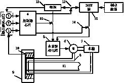
[0010] A schematic diagram of the structure of a new hub motor heat dissipation controller, such as figure 1 shown. Mainly include SOC estimator, brake pedal sensor, temperature sensor, controller chip, water pump drive circuit, water pump, water tank, pipeline, wheel, hub motor, axle, battery, relay A, relay B, relay C, IGBT bridge, The controller chip judges whether to use the braking energy for the hub motor to dissipate heat by collecting the output status of each sensor.

[0011] figure 1 The initial state of each relay is that relay A is normally closed, relay B is normally open, and relay C is normally open.

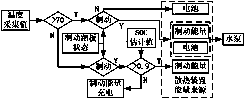
[0012] The specific logic control block diagram is as follows: figure 2 As shown, the specific logic is to first judge whether the temperature of the hub motor is higher than the set value of 70°C, if it is higher than the set value, the relay C is clos


PUM


Abstract

The invention designs a novel wheel hub motor heat radiation controller by combining a braking energy recovery system, which full utilizes braking energy to solve the problem of motor heat radiation.The novel wheel hub motor heat radiation controller comprises a signal acquisition circuit, a controller chip and a water pump drive circuit. Based on the braking status monitored by the signal acquisition circuit in real time, battery SOC estimation value and hub motor temperature status, the controller chip controls the water pump drive circuit to drive the pump to continuously circulate the coolant, therefore, achieving the hub motor cooling function, reducing the hub motor temperature, reducing motor losses, increasing the life of the motor and vehicle battery and improving brake energy utilization.

Description


Claims


Application Information

Patent Timeline
Owner CHANGCHUN UNIV OF TECH
Why Eureka
Try Eureka