Projection robot

A robot and machine technology, applied in the field of intelligent robots, can solve problems such as fixed projection angle, limited application range, unfavorable changes in projection angle, etc., to achieve the effect of improving product quality and expanding the field of use

Pending Publication Date: 2018-05-29
GOERTEK INC
View PDF0 Cites 6 Cited by
  • Summary
  • Abstract
  • Description
  • Claims
  • Application Information

AI Technical Summary

Problems solved by technology

[0003] However, the structure of the traditional projection robot is relatively simple, and the projection angle is relatively fixed, which is not conducive to the user to change the projection angle according to different application

Method used


Image

  • Projection robot
  • Projection robot
  • Projection robot

Examples


specific Embodiment

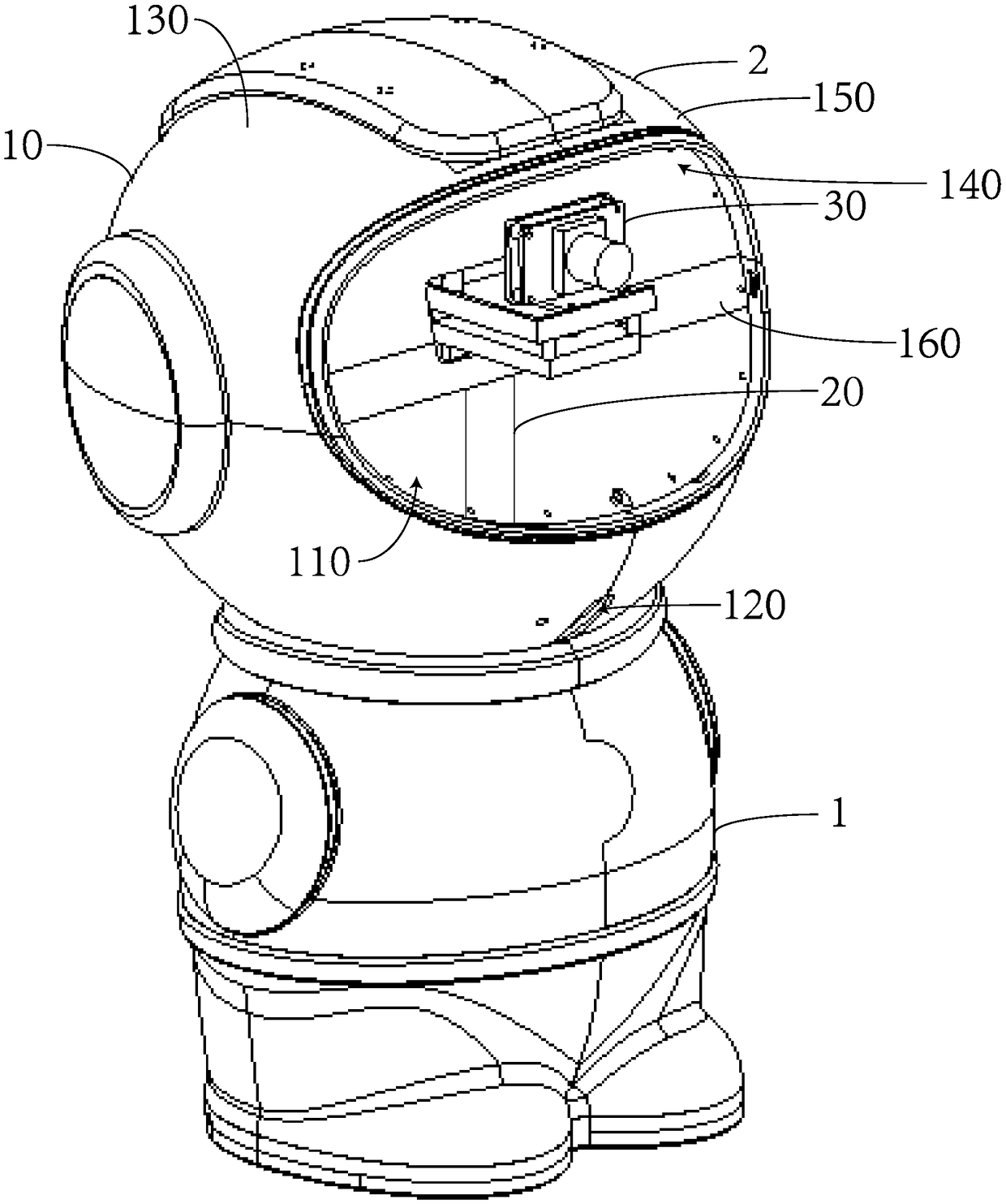
[0035] Please refer to figure 1 , is a three-dimensional schematic diagram of the projection robot provided by the embodiment of the present invention. The projection robot includes a robot body 1 and a robot head 2 . The robot head 2 is located above the robot body 1 and is movably connected with the robot body 1 .

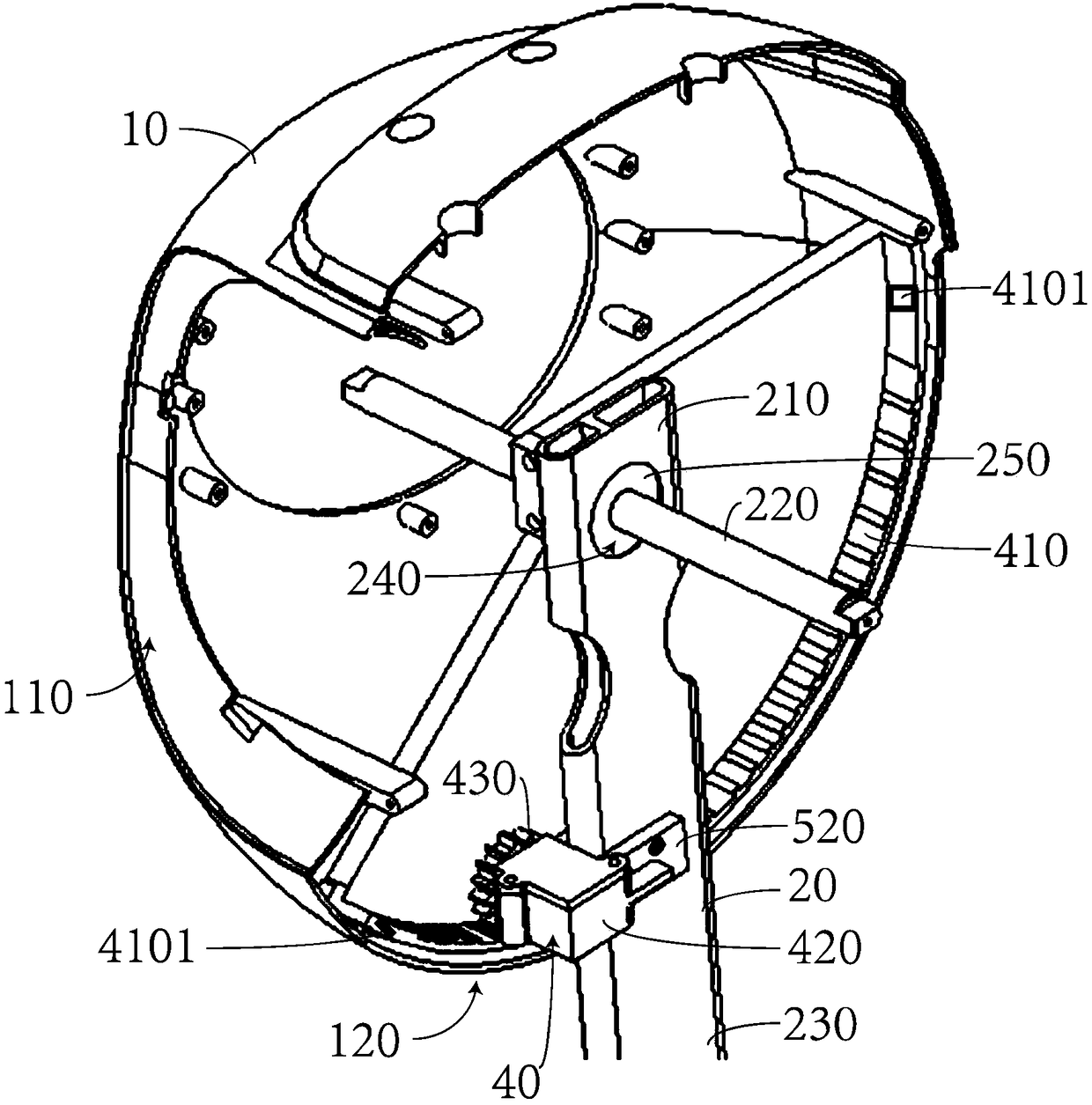
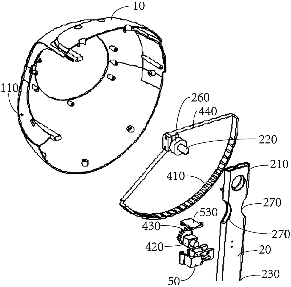
[0036] and combine figure 2 , the robot head 2 includes a housing 10 , a bracket 20 , a projection module 30 and a transmission assembly 40 that drives the housing 10 to move on the robot body 1 . The projection module 30 is arranged in the casing 10, and the casing 10 is provided with a projection window 110 in the projection direction of the projection module 30, and a slideway 120 is also provided on the casing 10; The rack track 410 linked with the housing 10, the motor 420 mounted on the bracket 20, and the gear 430 arranged on the shaft head of the motor 420, the gear 430 meshes with the rack track 410; the first end 210 of the bracket 20 is located in the h


PUM


Abstract

The invention discloses a projection robot which comprises a robot body part and a robot head part which is movably connected with the robot body part. The robot head part comprises a shell, a support, a projection module and a transmission assembly driving the shell to move on the robot body part. The projection module is arranged in the shell and provided with a projection window in the projection direction, and a slideway is further formed in the shell. The transmission assembly comprises a rack rail which is arranged along the slideway and linked with the shell, a motor mounted on the support, and a gear arranged on a shaft head of the motor. The gear is engaged with the rack rail. The first end of the support is located in the shell, and an assembly shaft used for assembling the shellis connected to the first end. The second end of the support penetrates through the robot head part to extend to the robot body part and is fixed to the inner side of the robot body part. The gear rotates under driving of the motor, and the shell is driven through the rack rail to move relative to the support. According to the projection robot, the technical problems that a traditional projectionrobot is simple in structure and fixed in projection angle are solved.

Description


Claims


Application Information

Patent Timeline
Owner GOERTEK INC
Why Eureka
Try Eureka