Coil panel seat, coil panel and electromagnetic cooking utensil

A technology for cooking utensils and coil discs, which is applied to coil devices, cooking utensils, electric/magnetic/electromagnetic heating, etc., can solve the problems of scattered heating areas, high local temperature, and inability to dissipate heat and air flow.

Pending Publication Date: 2018-06-05
FOSHAN SHUNDE MIDEA ELECTRICAL HEATING APPLIANCES MFG CO LTD
View PDF0 Cites 0 Cited by
  • Summary
  • Abstract
  • Description
  • Claims
  • Application Information

AI Technical Summary

Problems solved by technology

[0003] There are multiple winding slots on the multi-loop coil disk, and multiple winding slots and heating coils form multiple heating areas. The heating rate of multiple heating areas is faster, but multiple heating areas also lead to the multi-loop coil disk working When the heating area is dispersed, the cool

Method used


Image

  • Coil panel seat, coil panel and electromagnetic cooking utensil
  • Coil panel seat, coil panel and electromagnetic cooking utensil
  • Coil panel seat, coil panel and electromagnetic cooking utensil

Examples


Embodiment Construction

[0023] The following will clearly and completely describe the technical solutions in the embodiments of the present invention with reference to the accompanying drawings in the embodiments of the present invention. Obviously, the described embodiments are only part of the embodiments of the present invention, not all of them. Based on the embodiments of the present invention, all other embodiments obtained by persons of ordinary skill in the art without creative efforts fall within the protection scope of the present invention.

[0024] It should be noted that if there is a directional indication (such as up, down, left, right, front, back...) in the embodiment of the present invention, the directional indication is only used to explain the position in a certain posture (as shown in the accompanying drawing). If the specific posture changes, the directional indication will also change accordingly.

[0025] In addition, if there are descriptions involving "first", "second" and so


PUM


Abstract

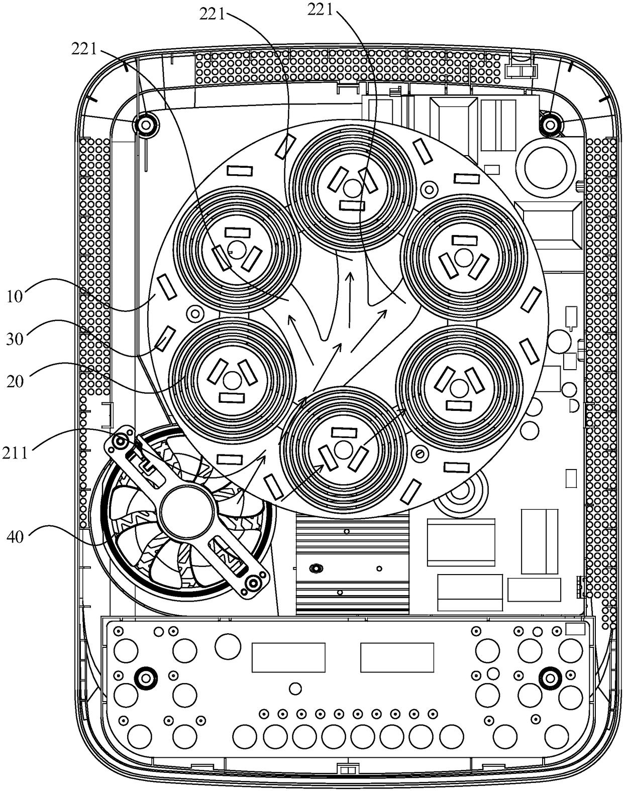
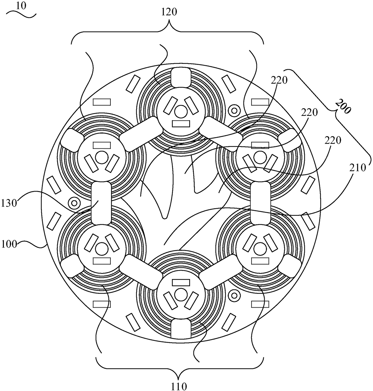
The invention discloses a coil panel seat, a coil panel and an electromagnetic cooking utensil. The coil panel seat comprises a panel seat body and a wind guide channel, wherein a plurality of wire wrapping grooves are formed in the panel seat body, the plurality of wire wrapping grooves comprise a plurality of first wire wrapping groove arranged along the draft direction and a plurality of secondwire wrapping grooves deviating from the draft direction; the wind guide channel is arranged on the panel seat body, the wind guide channel comprises an air inlet and an air outlet, the air inlet isformed corresponding to the draft wind direction, the air outlet is connected with the second wire wrapping grooves to guide the air flow of a radiator fan to the second wire wrapping grooves. The coil panel seat can guide the air flow of the radiator fan to the second wire wrapping grooves through the wind guide channel, thus the heat dissipation of the second wire wrapping grooves is promoted, so that the temperature of each heating area is consistent, and the heating effect of the coil panel seat is improved.

Description


Claims


Application Information

Patent Timeline
Owner FOSHAN SHUNDE MIDEA ELECTRICAL HEATING APPLIANCES MFG CO LTD
Why Eureka
Try Eureka