Air outlet structure for air conditioner equipment, control method and air conditioner equipment

A technology for air conditioning equipment and air outlet direction, which is applied to heating and ventilation control systems, mechanical equipment, air flow control elements, etc. and other problems to achieve the effect of improving comfort

Inactive Publication Date: 2016-11-09
GREE ELECTRIC APPLIANCES INC
View PDF8 Cites 9 Cited by
  • Summary
  • Abstract
  • Description
  • Claims
  • Application Information

AI Technical Summary

Benefits of technology

In this new design, there are two main components: one includes a fan unit with rotating blades called pump parts inside it; another component consists of an adjustable part where some kind of mechanism allows them to be moved backward/forward within its own body. These mechanisms allow fans to rotate around their axis at various points along their length, allowing more space between these elements when they work together. By doing this, the system provides flexible options for supplying coolant into specific areas based upon how well each area has been cooled down after being used.

Problems solved by technology

The technical problem addressed by this patented technology relates to improving the design of current wall- mounted air conditioners without sacrificing their performance or functionality due to limitations such as poor thermal management capabilities caused by insufficient air flow through the device when cold weather conditions occur.

Method used


Image

  • Air outlet structure for air conditioner equipment, control method and air conditioner equipment
  • Air outlet structure for air conditioner equipment, control method and air conditioner equipment
  • Air outlet structure for air conditioner equipment, control method and air conditioner equipment

Examples


Embodiment Construction

[0031] The present invention will be described in detail below. In the following paragraphs, different aspects of the embodiments are defined in more detail. Aspects so defined may be combined with any other aspect or aspects unless specifically stated otherwise. In particular, any feature considered to be preferred or advantageous may be combined with one or more other features which are considered to be preferred or advantageous.

[0032] Terms such as "first" and "second" appearing in the present invention are only for convenience of description, to distinguish different components with the same name, and do not indicate a sequence or a primary and secondary relationship.

[0033] In the description of the present invention, the orientations or positional relationships indicated by "up", "down", "left" and "right" are based on the orientations or positional relationships shown in the drawings, and are only for the convenience of describing the present invention , rather than


PUM


Abstract

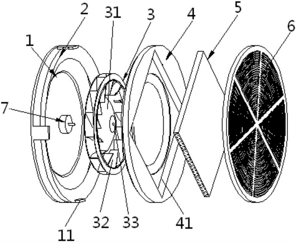
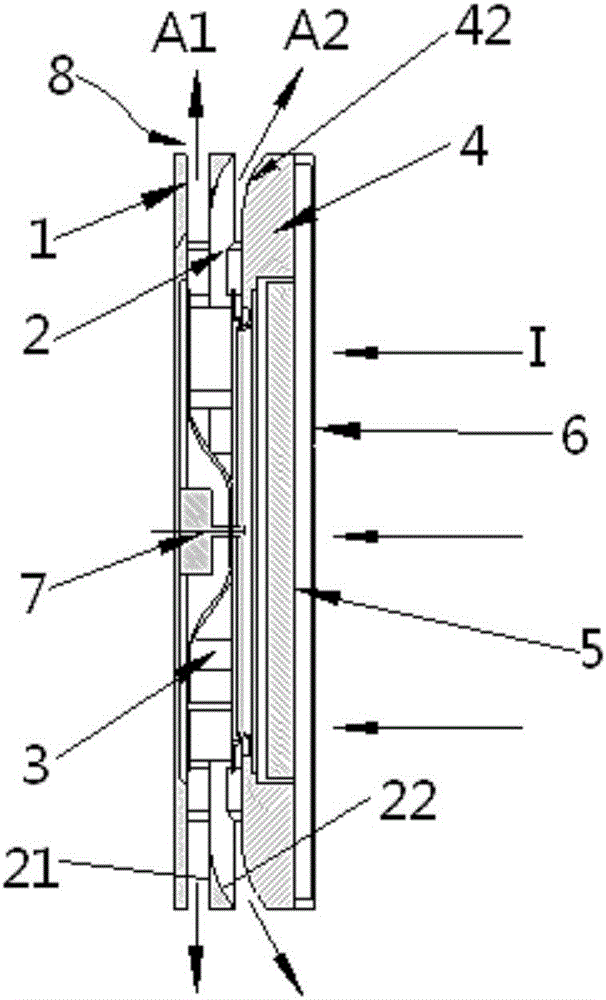
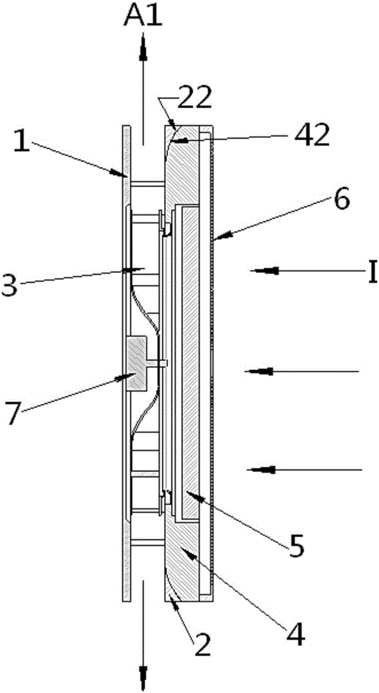
The invention relates to an air outlet structure for air conditioner equipment, a control method and the air conditioner equipment. The air outlet structure for the air conditioner equipment comprises a shell, a centrifugal air suction part and an adjusting part; the shell is provided with an air outlet (8); the centrifugal air suction part is arranged in an air duct of the air conditioner equipment and used for leading airflow in the air duct to the air outlet (8) in the shell to achieve air outflow in the circumferential direction; and the adjusting part is arranged in the air outlet (8) and can adjust the angle of an air flow channel in the manner that the adjusting part moves relative to the air outlet (8), and therefore the air outflow direction can be changed. The air outlet structure for the air conditioner equipment can adopt air supply manners at different angles according to different requirements, so that the comfort degree feeling of a user can be improved as much as possible, or the regional selection requirement of the user for refrigerating and heating can be met.

Description


Claims


Application Information

Patent Timeline
Owner GREE ELECTRIC APPLIANCES INC
Why Eureka
Try Eureka