Ventilator for freight container

a technology for ventilating containers and freight containers, which is applied in the direction of functional valve types, containers, heating types, etc., can solve the problems of spoiled goods and possible corrosion of the interior of the container

Inactive Publication Date: 2008-11-13
DURALOC
View PDF5 Cites 9 Cited by
  • Summary
  • Abstract
  • Description
  • Claims
  • Application Information

AI Technical Summary

Benefits of technology

The technical effect that this design allows for better control over how fluids are moved between two areas within an aircraft cargo space during flight operations by controllably blocking off certain parts or sections of it's airflow pathways. This helps improve safety measures such as ensuring proper ventilation while minimizing any potential hazards caused when there may be other objects entering through these openings.

Problems solved by technology

In this patented technical solution described in the current embodiment of the Venturinor Device (VCD) proposed onboard ships during cargo handling operations, there exist issues related to ensuring proper ventilation while also protecting against damage from rainwater impacts due to high pressure waves caused by ocean currents.

Method used


Image

  • Ventilator for freight container
  • Ventilator for freight container
  • Ventilator for freight container

Examples


Embodiment Construction

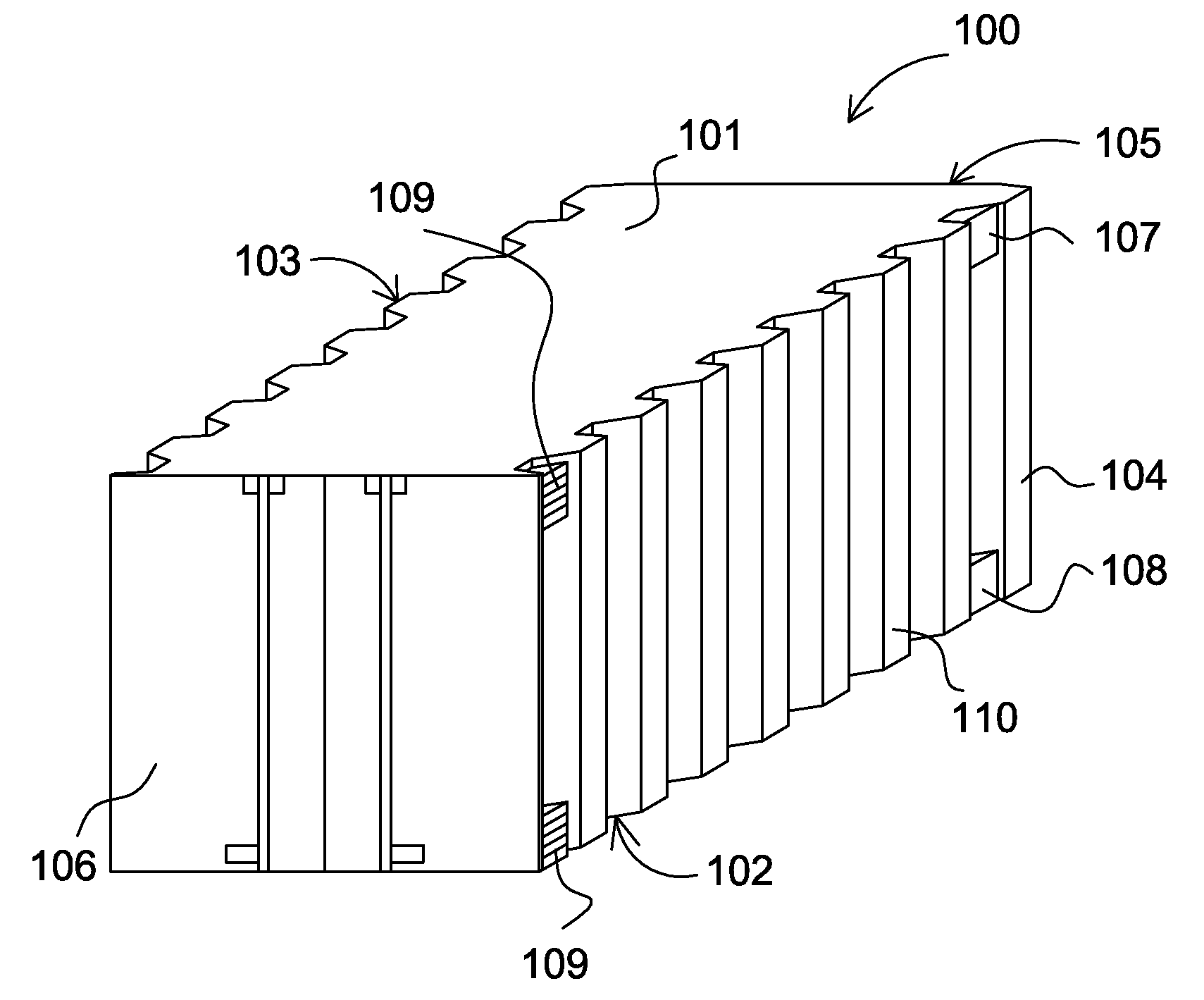
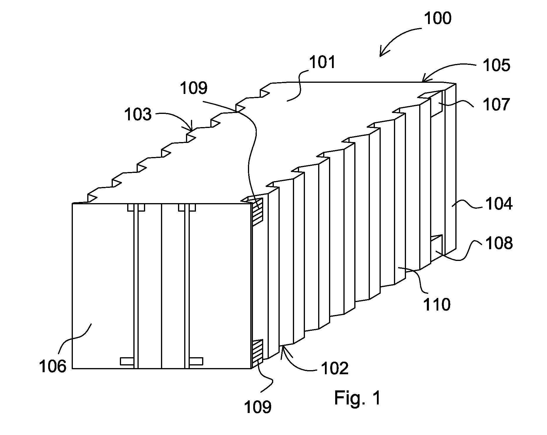
[0039]Referring to FIG. 1, the freight container is substantially cuboidal comprising roof 101, floor 102, side walls 103, 104, 105 and doors 106 positioned opposed side wall 105. The side walls with the largest surface area 103, 104 comprise corrugations 110 extending vertically between roof 101 and floor 102. An air flow vent 107 is positioned at each uppermost corner of side walls 103, 104 to provide air flow into the interior of the container 400, referring to FIG. 4. Alternatively or in addition, a plurality of air flow vents 108 may be provided at each lowermost corner of container 100 on each of the largest faces 103, 104.

[0040]Container 100 comprises a ventilator device 109 positioned over the upper and / or lower air flow vents 107, 108. The ventilator device effectively covers the vents 107, 108 such that air flowing into the freight container interior 400 must pass through the ventilator device 109 interfaced with each air flow vent 107, 108.

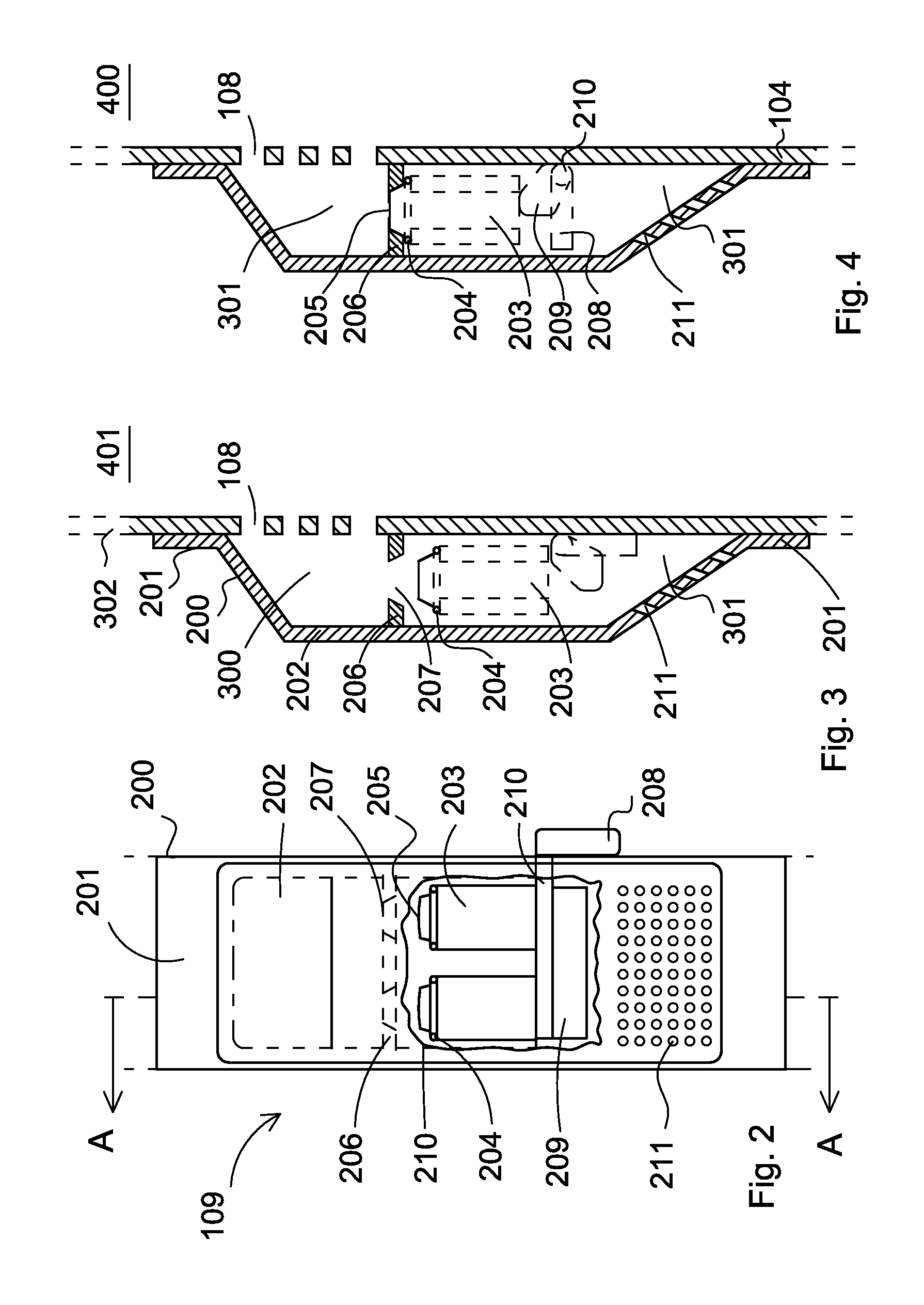
[0041]Referring to FIGS. 2 to 4,


PUM


Abstract

A ventilator device for a freight container configured to prevent the ingress of water into the cargo tank interior. The ventilator device comprises a floatation-based valve configured to shuttle backwards and forwards in response to contact with water. The valve acts to open and close the air flow passageway through the device and is mounted over the air flow vents of the container. A manual override actuator may be provided to manually open and close the valves.

Description


Claims


Application Information

Patent Timeline
Owner DURALOC
Why Eureka
Try Eureka