Optical fiber laying and imaging device and method for sensing phreatic surface of dam

A technology of imaging device and wetting surface, applied in the direction of measuring device, lubrication indicating device, mechanical equipment, etc., can solve the problems of increased cost of buried monitoring instruments and increased monitoring workload.

Inactive Publication Date: 2018-06-12
HOHAI UNIV
View PDF4 Cites 4 Cited by
  • Summary
  • Abstract
  • Description
  • Claims
  • Application Information

AI Technical Summary

Benefits of technology

This technology allows for better understanding about how water can be slicked off from areas where there are no pipes or other features that help it flow smoothly through them compared to previous methods like adding fiber cables inside walls. By inserting these fibers into specific parts within each section along their edges, they create an even layer overall, which helps prevent damage caused by excessive rainwater runoff.

Problems solved by technology

This patented technology involves combining two different techniques - Optical Fiber Layered Layout (OFTL) and Gridless Center Gravity Interpolating Method(GCAI). These technologies allow us to continuously measure the depth or thickness of any cracks formed by tunneling rainwater into concrete floors without requiring expensive equipment. They are particularly useful because they provide quicker response times than current methods like ultrasound scanning but still have their advantages over older methods such as visual inspections.

Method used


Image

  • Optical fiber laying and imaging device and method for sensing phreatic surface of dam
  • Optical fiber laying and imaging device and method for sensing phreatic surface of dam
  • Optical fiber laying and imaging device and method for sensing phreatic surface of dam

Examples


specific Embodiment approach

[0041] The specific implementation method comprises the following steps:

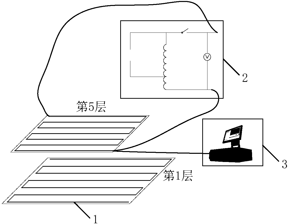
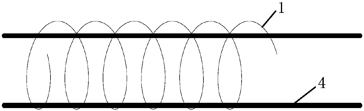
[0042] (1) Lay the optical fiber 1 in 5 layers in the embankment, press shape and shapes to alternate laying and embedding, such as figure 1 As shown, the vertical channel is spirally fixed on the steel support 4 to the optical fiber 11, such as figure 2 As shown, the outer layer of the steel support is coated with a multi-layer flexible resin coating with extremely high elasticity and high thermal conductivity, preferably polyethersulfone material PSF-F-51, and the armored optical cable ZTT-GYXTW- for the specific monitoring optical fiber 1 4Ala, which is a 50 / 125um multi-mode four-core with built-in steel wire reinforcement;

[0043] (2) The pulse emitting device 2 of this embodiment is a pulse laser device, which is connected with a 50 / 125 multimode optical fiber 1 and outputs a 10 nanosecond optical pulse, whose tail is connected with an E2000 fiber optic connector, and the optical fiber 1 i


PUM


Abstract

The invention discloses an optical fiber laying and imaging device and method for sensing a phreatic surface of a dam. The device comprises at least five layers of optical fibers laid layer by layer along the height direction of the dam, the optical fibers laid layer by layer along the height direction of the dam are alternately laid according to the shape as shown in the description, one ends ofthe optical fibers are connected with a pulse transmitting device, and the other ends of the optical fibers are connected to a computer through an optical fiber connector. The device obtains points ona phreatic line of different sections by means of layered laying of the distributed optical fibers, interpolating point distribution is conducted on center of gravity in the area, iterative computation is conducted to form the phreatic line, the points on the different sections are connected to generate the complete phreatic surface, and the device has a great significance in achieving the wholeregion real-time monitoring of seepage behavior of the dam.

Description


Claims


Application Information

Patent Timeline
Owner HOHAI UNIV
Why Eureka
Try Eureka