Surface recycling light-emitting position indicator for underwater equipment

An underwater equipment and water surface technology, applied in marine signal devices, transportation and packaging, ships, etc., can solve problems such as environmental degradation, unfavorable discovery of equipment, equipment salvage and recovery, etc., and achieve strong adaptability

Inactive Publication Date: 2018-07-27
SHANXI UNIV
View PDF7 Cites 6 Cited by
  • Summary
  • Abstract
  • Description
  • Claims
  • Application Information

AI Technical Summary

Problems solved by technology

[0002] The world is currently facing three major problems: population expansion, environmental degradation and resource shortage
Due to the complex marine environment and the lack of reference objects, underwater equipment generally ha

Method used


Image

  • Surface recycling light-emitting position indicator for underwater equipment
  • Surface recycling light-emitting position indicator for underwater equipment
  • Surface recycling light-emitting position indicator for underwater equipment

Examples


Embodiment Construction

[0021] The present invention is described in detail below in conjunction with accompanying drawing:

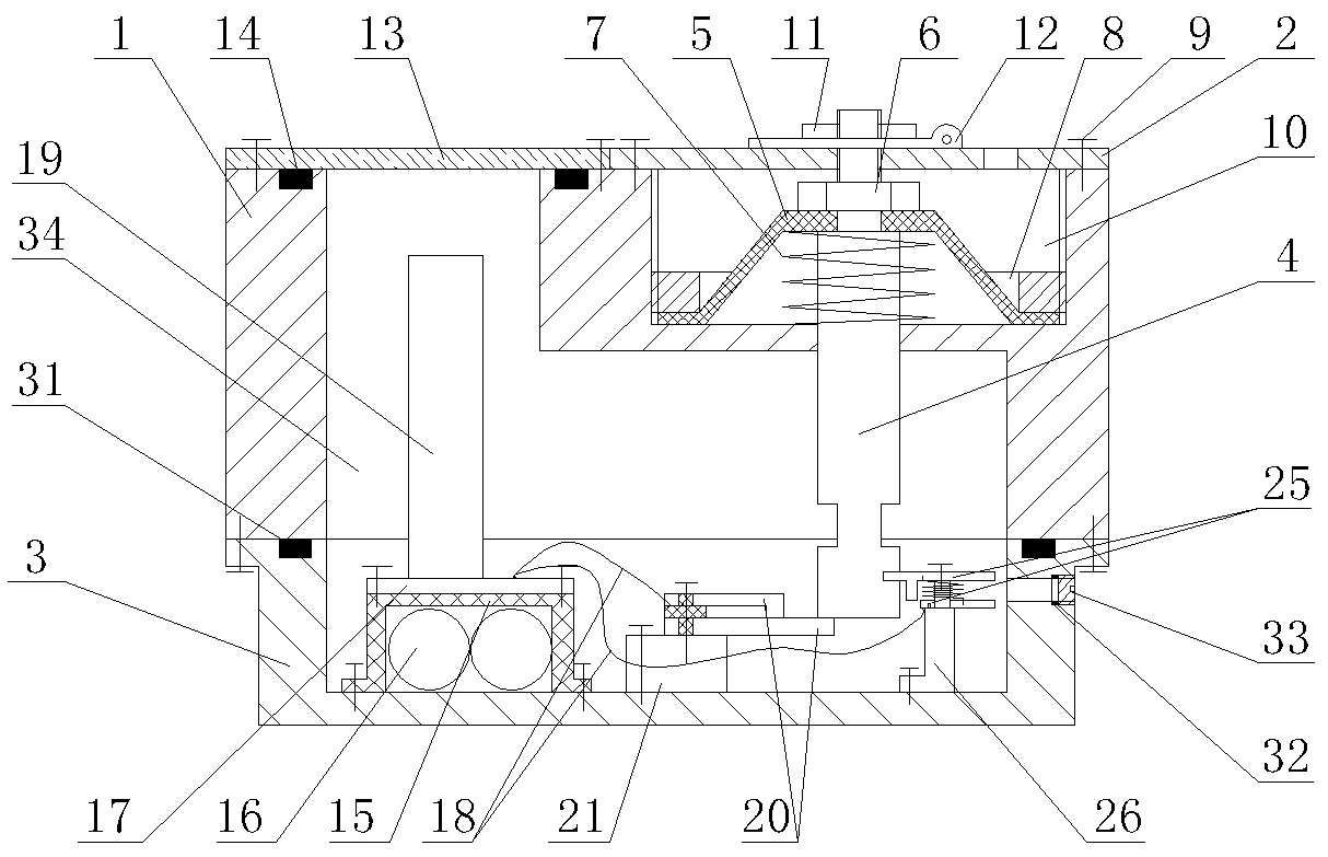
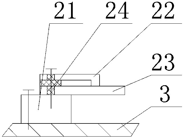
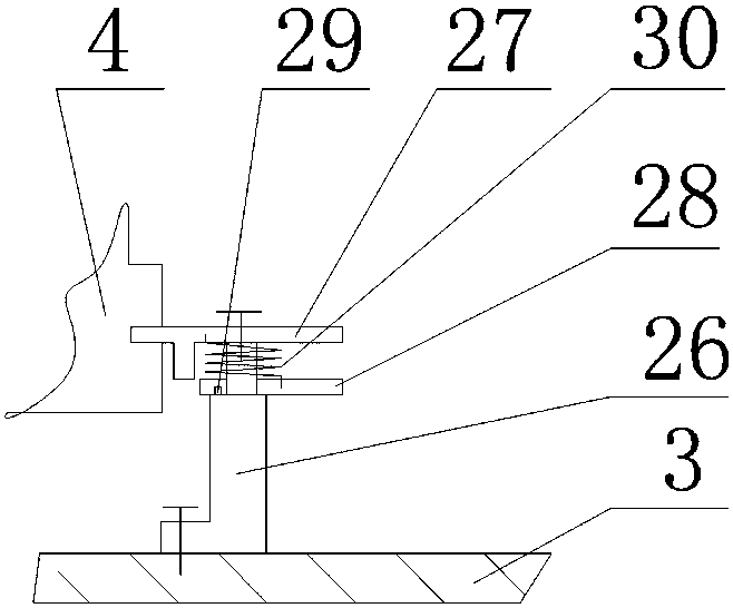
[0022] The present invention includes a base body 1, an upper cover plate 2, a lower cover plate 3, a hydraulic pressure rod 4, a hydraulic pressure film 5, a nut 6, a hydraulic pressure spring 7, a pressure ring 8, a screw 9, a cavity I 10, a round table 11, and a safety pin 12. Glass cover plate 13, sealing gasket I14, battery box 15, battery 16, circuit board 17, wire 18, light emitting tube 19, reversible normally closed contact group 20, insulating table I21, upper contact piece I22, lower contact Sheet Ⅰ23, insulating sheet 24, normally open contact group 25, insulating platform Ⅱ26, upper contact sheet Ⅱ27, lower contact sheet Ⅱ28, limit pin 29, torsion spring 30, sealing gasket Ⅱ31, sealing gasket Ⅲ32, screw plug 33 and cavity II34. The hydraulic pressure rod 4 passes through the round hole provided by the middle part of the right cavity of the base body 1 and is loaded


PUM


Abstract

The invention belongs to the technical field of equipment fishing and recycling devices and particularly relates to a surface recycling light-emitting position indicator for underwater equipment, comprising a base, an upper cover plate, a lower cover plate, a hydraulic rod, a hydraulic membrane, a nut, a hydraulic spring, a compression ring, screws, chamber I, a circular terrace, a safety pin, a glass cover plate, seal gasket I, a battery box, a battery, a circuit board, wires, a light-emitting tube, a reversible normally-closed contact unit, insulating terrace I, upper contact plate I, lowercontact plate I, an insulating sheet, a normally-opened contact unit, insulating terrace II, upper contact plate II, lower contact plate II, a limiting pin, a torsion spring, seal gasket II, seal gasket III, a screw plug, and chamber II. The surface recycling light-emitting position indicator for underwater equipment indicates a position vividly by emitting light at water surface and can provide avivid indication particularly when equipment emerges from water at night.

Description


Claims


Application Information

Patent Timeline
Owner SHANXI UNIV
Why Eureka
Try Eureka