Tension stabilizing device and tension stabilization control method in horizontal floating mode

A stable control method and a stable device technology, applied in tension/pressure control, metal rolling, etc., can solve problems such as failure to meet precision requirements, and achieve the effect of wide tension adjustment range and high tension control precision

Pending Publication Date: 2018-08-03
HUANGSHI SUNNY SCI & TECH CO LTD
View PDF8 Cites 2 Cited by
  • Summary
  • Abstract
  • Description
  • Claims
  • Application Information

AI Technical Summary

Benefits of technology

In this invention there are two technical features: one uses air spring technology for controlling the movement of rollers while another automatically controls them by an electrical signal based on feedback from sensors that monitor the level of force applied onto the roller's surface (known as load). By doing both these techniques together they achieve high tensional stability and precise sheet width control over various processes such as rolling mill processing.

Problems solved by technology

The technical problem addressed in this patented text relates to controlling the tensional force applied during hot dip coating processes used in manufacture of metal products such as household electrical devices (HEs). When changing from one type of process to another without affecting its performance, there may occur changes made due to factors like temperature variations over different areas inside the chamber where molten zinc flows through. These issues lead to tendederness and damage caused by excessive tensile stress at certain points along the width direction of the sheet being treated. To address these concerns, current methods involve tightening down the belt' s position with pressure rollers near each side of the heated zone. By monitoring the tonal forces developed across multiple locations throughout the entire treatment area, feedback loops can help keep the tarp level properly even under varying conditions.

Method used


Image

  • Tension stabilizing device and tension stabilization control method in horizontal floating mode
  • Tension stabilizing device and tension stabilization control method in horizontal floating mode
  • Tension stabilizing device and tension stabilization control method in horizontal floating mode

Examples


no. 1 example

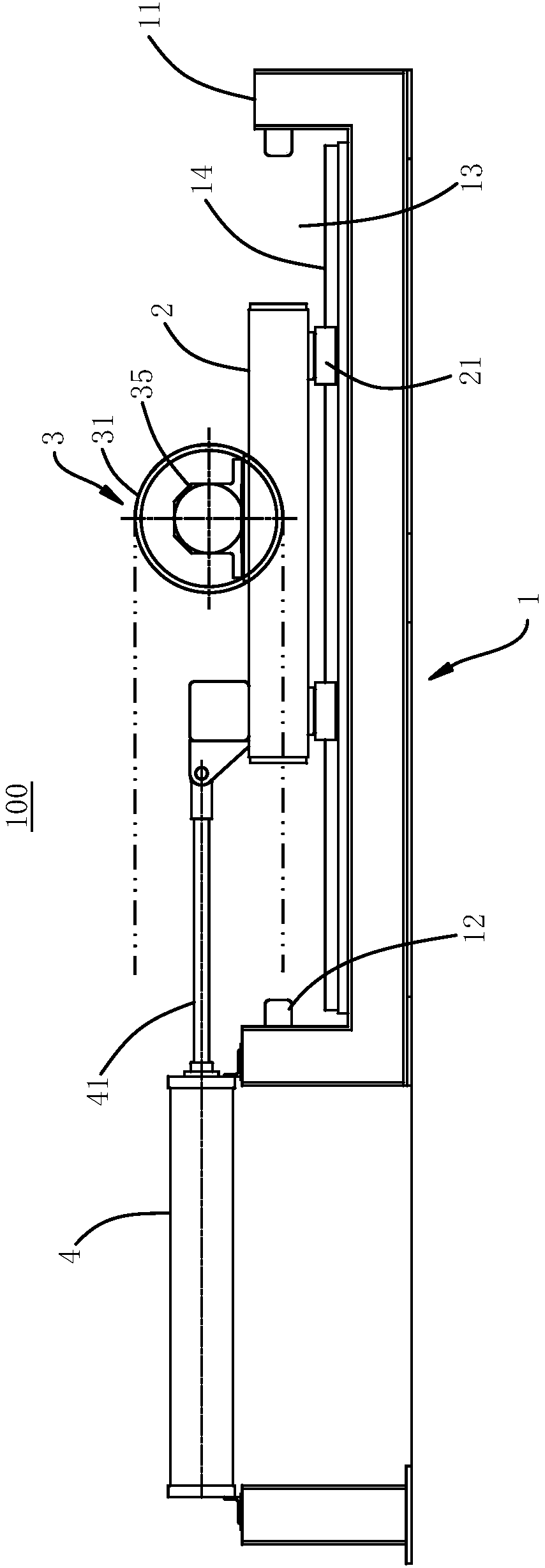
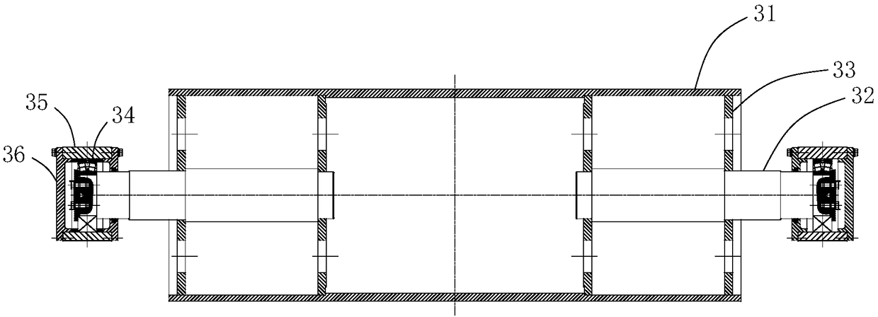
[0039] Please refer to figure 1 , this embodiment provides a horizontal floating tension stabilization device 100, which is applied between the tension roller 5 and the tension roller 6 in front of the furnace, and includes a fixed base 1, a floating base 2 located on the fixed base 1, and a The buffer roller 3 of the floating base 2, the driving assembly connected with the floating base 2, and the control assembly connected with the driving assembly.

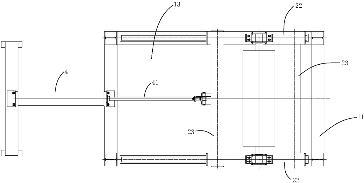
[0040] Such as Figure 1-Figure 4 As shown, in this embodiment, the fixed base 1 is provided with a guide portion 14, and the guide portion 14 extends along the advancing direction of the steel strip, and the floating base 2 is provided with a connecting portion 21 that cooperates with the guide portion 14, and the connecting portion 21 is connected to the guide portion. part 14, so that the floating base 2 can move relative to the fixed base 1 on the fixed base 1 along the guide part 14; The output end of the output end is conn

no. 2 example

[0066] After research, the researchers found that the horizontal floating tension stabilization device 100 provided by the present invention, on the basis of the above-mentioned first embodiment, can also make the following optional other structural solutions, which are specifically described as follows:

[0067]The guide part 14 is a track, and the connecting part 21 includes at least four rollers. At least four rollers are distributed at both ends of the floating base 2 along the length direction of the guide part 14. The rollers are rotatably connected with the floating base 2, and the rollers are rotatably arranged. in the track.

[0068] The cooperation between the roller and the track improves the flexibility of movement of the floating base 2 and reduces the friction between the connecting part 21 and the guiding part 14 .

no. 3 example

[0070] After research, researchers have found that the horizontal floating tension stabilization device 100 provided by the present invention, on the basis of the above-mentioned first embodiment, can also make the following optional other structural solutions, which are specifically described as follows:

[0071] The guide part 14 is a rack, the connecting part 21 is a gear, the gear is rotatably connected to the floating base 2, and the gear and the rack mesh. The meshing of the gear and the rack improves the positioning accuracy of the connecting portion 21 and the guiding portion 14 and facilitates the movement of the floating base 2 relative to the fixed machine base 1 .


PUM


Abstract

The invention relates to a tension stabilizing device and a tension stabilization control method in a horizontal floating mode, and belongs to the technical field of cold rolling strip steel heat treatment. The horizontal floating mode tension stabilizing device is characterized in that a guide portion is arranged on a fixing machine base, a floating base is provided with a connecting portion matched with the guide portion, a buffer roller is rotatably connected with the floating base, strip steel enters an annealing furnace through a front tension roller, a buffer roller and a tension rollerin front of the furnace, a servo air cylinder can drive the floating base to move relative to the fixing machine base in the length direction of the guide portion, and the control assembly is used forcontrolling the working state of the driving assembly. The tension stabilizing device of the horizontal floating mode is used for reference to the principle of a pneumatic spring and is matched witha pneumatic pressure regulating and pressure stabilization automatic servo control system, so that closed-loop adjustment of the tension of the strip steel is realized in a mechanical buffering mode and the tension control precision is improved. According to the tension stabilization control method, the production efficiency is improved, and the requirements of users are met.

Description


Claims


Application Information

Patent Timeline
Owner HUANGSHI SUNNY SCI & TECH CO LTD
Why Eureka
Try Eureka