Compressor and air conditioning system

A compressor and piston technology, applied in the field of compressors, can solve problems such as large friction loss and decreased compressor efficiency, and achieve the effects of reducing friction loss, reducing friction power loss, and improving mechanical efficiency

Inactive Publication Date: 2018-08-14
SHANGHAI HITACHI ELECTRICAL APPLIANCES CO LTD
View PDF7 Cites 0 Cited by
  • Summary
  • Abstract
  • Description
  • Claims
  • Application Information

AI Technical Summary

Benefits of technology

This new design for an improved compression mechanism used on both traditional refrigeration systems (refrigerators) or heat pumps has several benefits compared to previous designs that were previously possible due to increased energy consumption caused by lubricating oil leakage from bearings during operation. These improvements result in better mechanical efficacy over time without requiring frequent maintenance.

Problems solved by technology

This patented technical problem addressed in this patents relates to decreased energy consumption during operation (energy lost) while maintaining reliable performance of conventional rotary or other type of compressor systems. Frictional resistance refers to contact between two objects made up of materials like metal plugs and lubricants inside the compressive machine. These factors contribute to reducing energy usage compared to traditional methods such as oil immersion coolings.

Method used


Image

  • Compressor and air conditioning system
  • Compressor and air conditioning system
  • Compressor and air conditioning system

Examples


Embodiment Construction

[0027] Example embodiments will now be described more fully with reference to the accompanying drawings. Example embodiments may, however, be embodied in many forms and should not be construed as limited to the embodiments set forth herein; rather, these embodiments are provided so that this disclosure will be thorough and complete, and will fully convey the concept of example embodiments to those skilled in the art. The same reference numerals denote the same or similar structures in the drawings, and thus their repeated descriptions will be omitted.

[0028] The words expressing position and direction described in the present invention are all described by taking the accompanying drawings as an example, but changes can also be made according to needs, and all changes are included in the protection scope of the present invention.

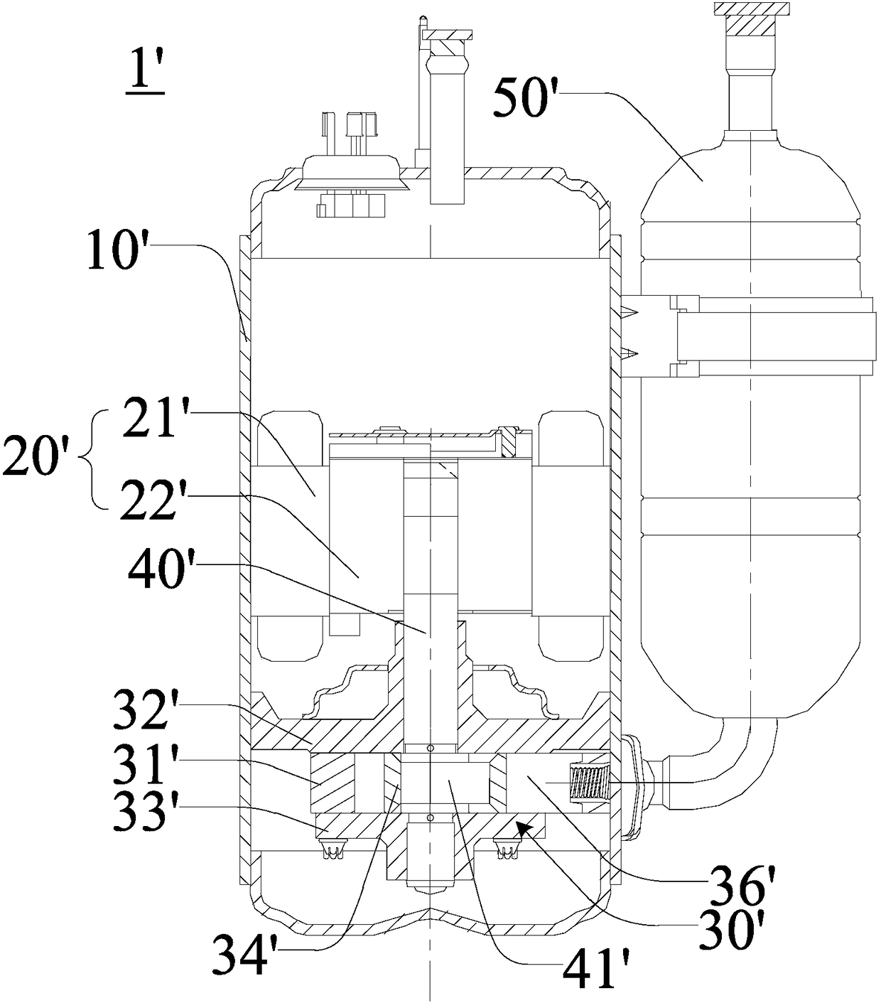
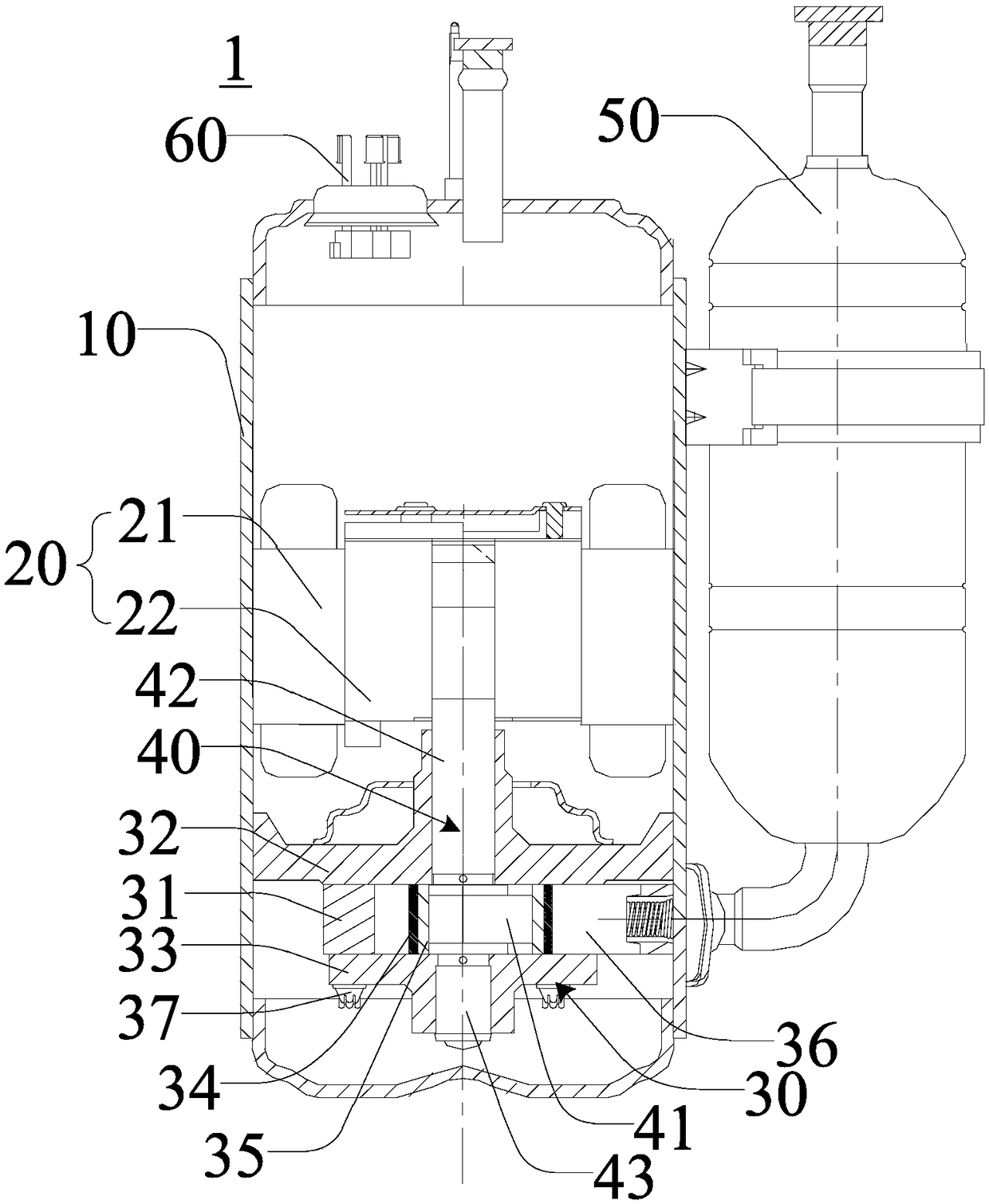
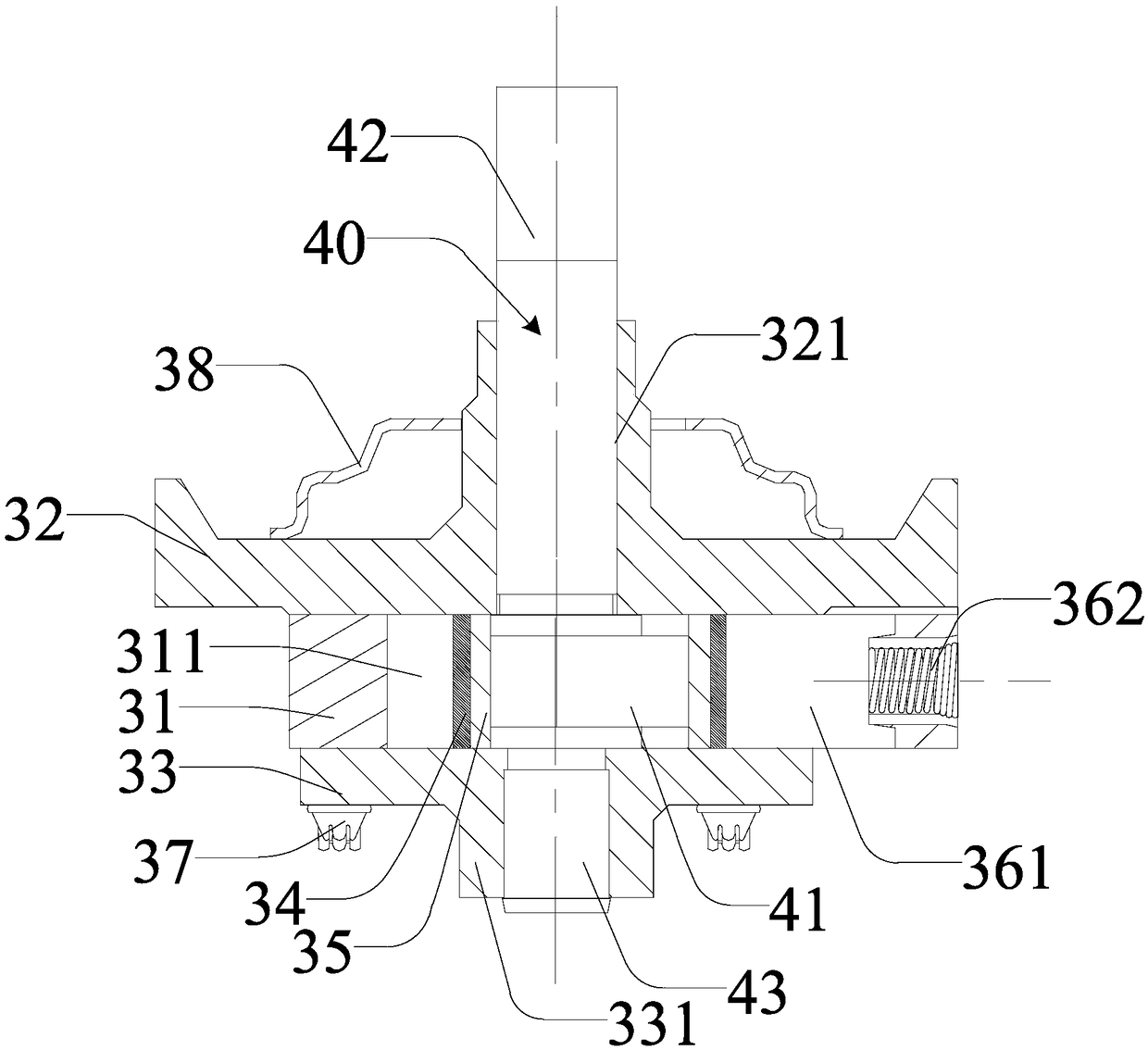
[0029] figure 2 is a schematic cross-sectional view of a compressor according to an embodiment of the present invention, image 3 It is a cross-s


PUM


Abstract

The invention discloses a compressor and an air conditioning system. The compressor comprises a pump body and a crankshaft having an eccentric part, wherein the pump body comprises: a gas cylinder, wherein the gas cylinder has a gas cylinder chamber and a blade groove positioned on the inner circumferential surface of the gas cylinder chamber; an upper cylinder cover and a lower cylinder cover forclosing the gas cylinder chamber; a first piston and a second piston positioned in the gas cylinder chamber, wherein the first piston is sleeved outside the second piston, the first piston and the second piston can slide opposite to each other, the second piston sleeve is sleeved outside the eccentric part of the crankshaft, and the second piston and the eccentric part of the crankshaft can slideopposite to each other; and a blade, wherein the blade projects out from the blade groove into the gas cylinder chamber, forms butt joint with the first piston, and separates the gas cylinder chamberinto a high pressure side and a low pressure side. With the compressor of the present invention, the friction loss between the piston and the eccentric part of the crankshaft can be reduced so as toimprove the mechanical efficiency of the compressor.

Description


Claims


Application Information

Patent Timeline
Owner SHANGHAI HITACHI ELECTRICAL APPLIANCES CO LTD
Why Eureka
Try Eureka