Direct-current charger model suitable for hardware-in-the-loop simulation system

A technology of simulation system and charger, applied in the direction of motor generator test, etc., can solve the problem that trigger test cannot be done at night, and the charging CAN communication test lacks accuracy and comprehensiveness.

Inactive Publication Date: 2018-08-14
BEIJING ZHIXING HONGYUAN AUTOMOBILE CO LTD
View PDF0 Cites 2 Cited by
  • Summary
  • Abstract
  • Description
  • Claims
  • Application Information

AI Technical Summary

Benefits of technology

This technology helps detect if there are problems with an electrical system that charges batteries for vehicles or other devices without actually shutting them down properly during maintenance work on their power supply unit (PDU). It does this by testing both regular communications between different components within the vehicle's battery pack while simulating its failures over time. By doing it correctly, they will be able to identify any issues beforehand which could lead to damage from unexpected events such as short circuits caused due to improper connections.

Problems solved by technology

This patented technical problem addressed in this patents relates to improving the quality control (QC) testing method used during the charge/discharge processes on batteries that use advanced electronic systems or hybrid powertrains. Current methods rely heavily upon physical connectors between different parts of the circuitry, making them difficult to accurately simulate realistic conditions under actual driving situations.

Method used


Image

  • Direct-current charger model suitable for hardware-in-the-loop simulation system

Examples


Embodiment Construction

[0028] The following will clearly and completely describe the technical solutions in the embodiments of the present invention with reference to the accompanying drawings in the embodiments of the present invention. Obviously, the described embodiments are only some, not all, embodiments of the present invention. All other embodiments obtained by persons of ordinary skill in the art based on the embodiments of the present invention belong to the protection scope of the present invention.

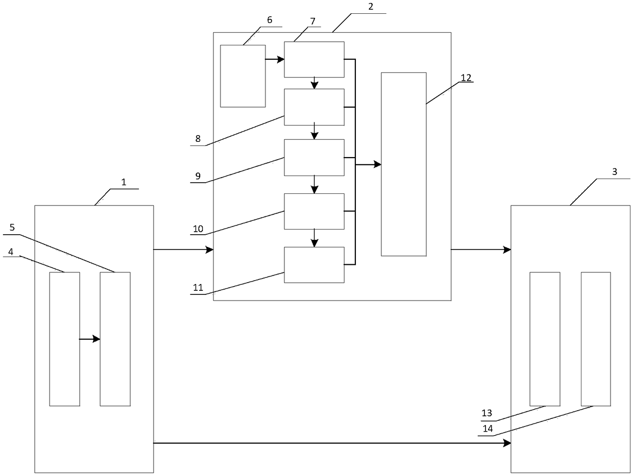
[0029] As shown in Figure 1, a DC charger model suitable for a hardware-in-the-loop simulation system according to an embodiment of the present invention includes a CAN message receiving layer 1, an application layer 2 and a CAN message sending layer 3, the The CAN message receiving layer 1 is connected with the application layer 2 and the CAN message sending layer 3, and the application layer 2 is connected with the CAN message sending layer 3;

[0030] Described CAN message receiving layer 1 c


PUM


Abstract

The invention discloses a direct-current charger model suitable for a hardware-in-the-loop simulation system. The model comprises a CAN message receiving layer, an application layer and a CAN messagesending layer; the CAN message receiving layer is connected with the application layer and the CAN message sending layer; and the application layer is connected with the CAN message sending layer. With the direct-current charger model suitable for the hardware-in-the-loop simulation system of the invention adopted, the normal communication of the direct-current charging CAN of a BMS (battery management system) can be tested, the fault of a whole communication process can be simulated, and whether the BMS can judge a fault and performs appropriate fault processing in the event of a fault can betested.

Description


Claims


Application Information

Patent Timeline
Owner BEIJING ZHIXING HONGYUAN AUTOMOBILE CO LTD
Why Eureka
Try Eureka