Rotating shaft braking device

A brake device and shaft technology, applied in the direction of brake types, drum brakes, gear transmission mechanisms, etc., can solve the problems of shaft braking, untimely response of operators, misoperation, etc., to facilitate rapid braking and avoid artificial The effect of misoperation and high response sensitivity

Inactive Publication Date: 2018-09-14
CHENGDU EXPERT OF BATTERY DESIGN TECH CO LTD
View PDF0 Cites 1 Cited by
  • Summary
  • Abstract
  • Description
  • Claims
  • Application Information

AI Technical Summary

Benefits of technology

This patented technology helps prevent damage or malfunctions caused by excessive rotation when turning off an electric motor's power supply during maintenance work on equipment such as machinery that uses it regularly over time. It achieves this without requiring manual interference from humans operators who may have incorrect responses or mistakes. Its main advantage being its simplicity and small size makes them easy to use with fast movements while still providing stable performance even at low speeds.

Problems solved by technology

In this patented technical problem addressed by the inventor's researchers during their experiments on an electric motor that uses a special type of gear called a spindle wheel (SPL) for transmitting power from one part of the machine to another without slipping or losing torque. This can be caused due to poor control over how quickly the SPL works with different speeds.

Method used


Image

  • Rotating shaft braking device
  • Rotating shaft braking device
  • Rotating shaft braking device

Examples


Embodiment 1

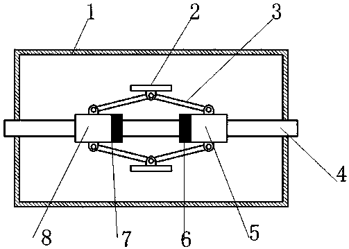
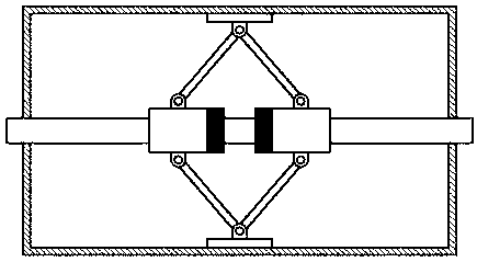
[0028] A rotating shaft braking device, which includes a braking cylinder 1, a rotating shaft 4 and a centrifugal mechanism; the rotating shaft 4 is inserted into the braking cylinder 1 and penetrates both ends of the braking cylinder 1, and the rotating shaft 4 is rotatably arranged on the braking cylinder 1; the centrifugal mechanism is rotatably arranged in the brake cylinder 1 and sleeved on the rotating shaft 4; the centrifugal mechanism includes a slider 1 5, a slider 2 8 and a number of friction blocks 2; the slider 1 5 The slider 2 is slidably sleeved on the rotating shaft 4 and moves along the axial direction of the rotating shaft 4; the top of each friction block 2 is used to contact the inner wall of the brake cylinder 1, and the bottom of each friction block 2 is hinged with two connecting The rod 3 and the two connecting rods 3 are hinged with the slider one 5 and the slider two 8 respectively;

[0029] like figure 1 and 2 As shown, the upper ends of the two connec

Embodiment 2

[0040] This embodiment is basically the same as the first embodiment, the difference is that the spherical surface of the ball 9 is in point contact with the inner wall of the groove 10 . like Figure 5As shown, the cross-section of the shaft section where the slider is installed is "cross"-shaped; the cross-sectional shape of the groove 10 is "V"-shaped, and the balls 9 are in point contact with both sides of the "V" shape; The point contact with the inner wall of the groove 10 can reduce the friction between the ball 9 and the groove 10 , which is more favorable for the slider to move on the groove 10 .


PUM


Abstract

The invention discloses a rotating shaft braking device. The rotating shaft braking device comprises a braking cylinder, a rotating shaft and a centrifugal mechanism; the rotating shaft is inserted into the braking cylinder, penetrates through the two ends of the braking cylinder and is arranged on the braking cylinder in a rotating mode; the centrifugal mechanism is arranged in the braking cylinder in a rotating mode, sleeves the rotating shaft and comprises a sliding block I, a sliding block II and a plurality of friction blocks; the sliding block I and the sliding block II sleeve the rotating shaft and move in the axial direction of the rotating shaft; two connecting rods are hinged to the bottom of each friction block and are hinged to the sliding block I and the sliding block II; an electromagnet I and an electromagnet II are arranged on the two opposite end surfaces of the sliding block I and the sliding block II; the electromagnet I is connected to a controller through a magnetic field intensity adjusting module I and a magnetic field direction adjusting module I; the electromagnet II is connected to the controller through a magnetic field intensity adjusting module II and amagnetic field direction adjusting module II; and a rotating shaft rotating speed detection sensor is further connected to the controller. According to the rotating shaft braking device, the rotatingshaft can be automatically braked under the condition of relatively high rotating speed.

Description


Claims


Application Information

Patent Timeline
Owner CHENGDU EXPERT OF BATTERY DESIGN TECH CO LTD
Why Eureka
Try Eureka