Intertidal zone sediment incipient motion measuring device and method

It is a technology of sediment starting and measuring device, which is applied in the direction of measuring device, fluid dynamics test, machine/structural component test, etc. It can solve the problems of small shear stress at the bottom and cannot reach the on-site measurement, and achieve accurate measurement results. Effect

Inactive Publication Date: 2018-09-14
HOHAI UNIV
View PDF6 Cites 4 Cited by
  • Summary
  • Abstract
  • Description
  • Claims
  • Application Information

AI Technical Summary

Benefits of technology

The technical effect of this new design for measuring suspended solids from water samples has several advantages over existing methods: it eliminates complicated equipment such as an oscillating machine or other tools used by older methods while still providing precise measurements. It also reduces interference between different types of particles caused by turbulence when they are being analyzed.

Problems solved by technology

This patented technical problem addressed in this patents relates to improving upon traditional techniques used for studying sediments such as hydraulic conductivity (HFC) analysis and turbidity detection. These conventional ways have limitations when trying to measure important parameters like particle size distribution and density contrast between different types of suspended matter. In order to overcome these issues, research has been done towards developing better systems for accurately determining key initial conditions called silt initiation pressure.

Method used


Image

  • Intertidal zone sediment incipient motion measuring device and method
  • Intertidal zone sediment incipient motion measuring device and method
  • Intertidal zone sediment incipient motion measuring device and method

Examples


Embodiment 1

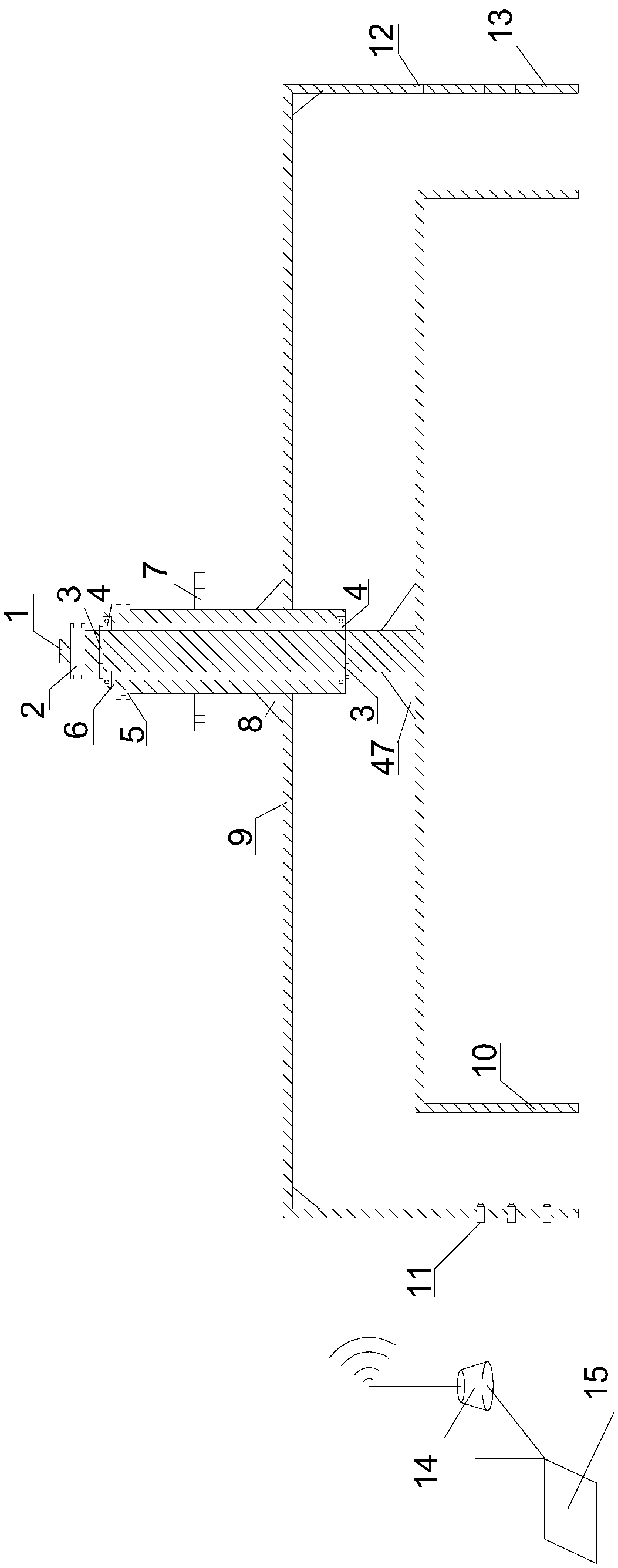
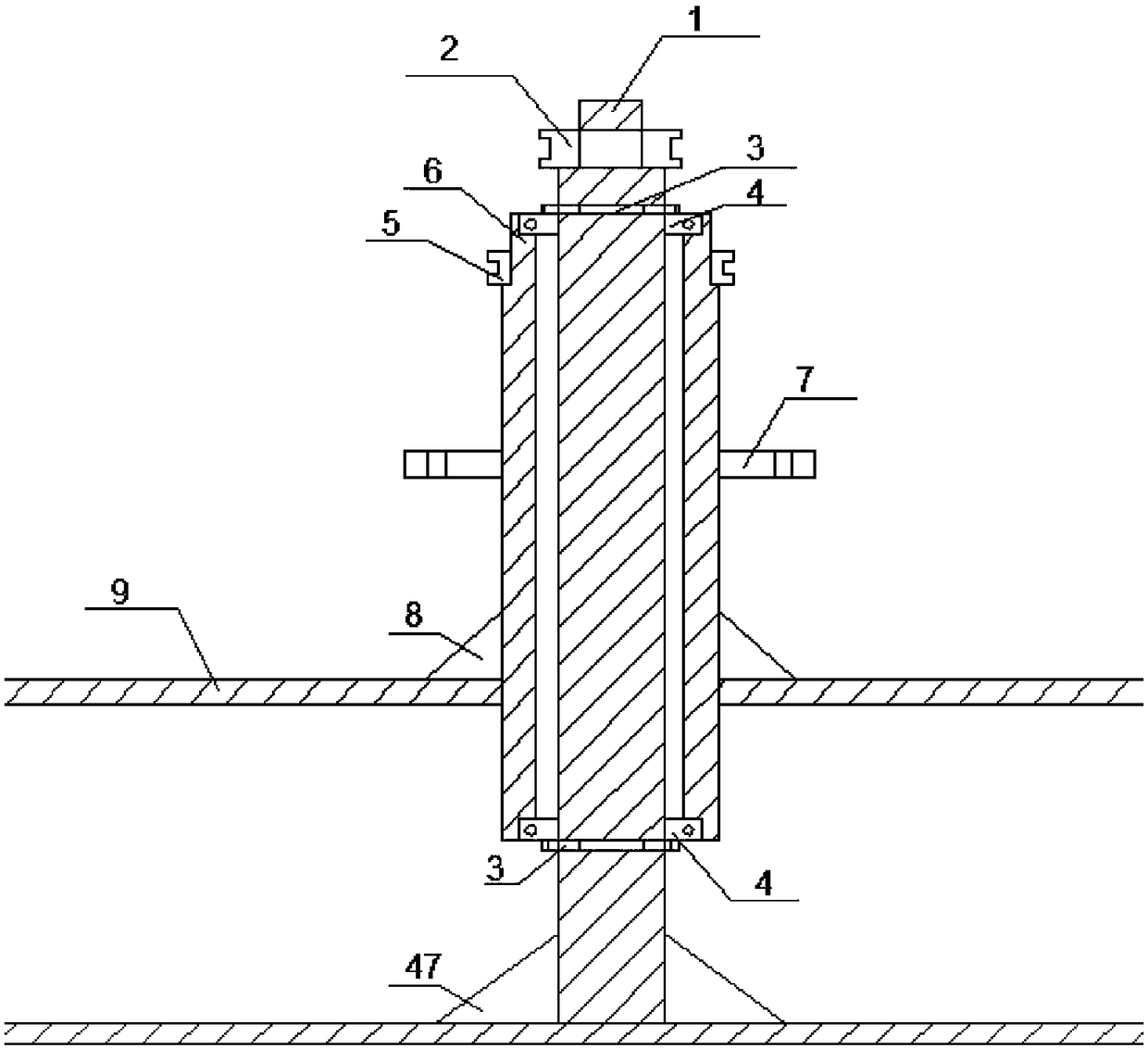
[0047] Such as figure 1 and 2 As shown, the upper structure of the device is mainly composed of a sleeve mandrel, an outer cylinder 9 made of plexiglass, and an inner cylinder 10 made of plexiglass. The sleeve mandrel includes an inner shaft 1 and an outer shaft 6, and the inner shaft 1 and the inner cylinder 10 is connected to each other through the first connecting rod 47 and the corner code, and the outer shaft 6 and the outer cylinder 9 are connected to each other through the second connecting rod 8 and the corner code; the inner shaft 1 and the outer shaft 6 are connected through the bearing 4, and the bearing 4 The outer side is clamped by the nut 3 to limit the movement of the bearing, and at the same time reduce the shaking of the shaft during rotation. The inner shaft 1 and the outer shaft 6 are respectively installed with the inner shaft pulley 2, the outer shaft pulley 5, and the outer shaft 6 A bearing shell 7 is set on the top; an OBS turbidity sensor 11 is installe

Embodiment 2

[0063] Define the optimum rotational speed ratio: for the instrument of measuring the starting stress of sediment for the radius r of the inner cylinder and the radius R of the outer cylinder, the radius r of the inner disc is 46 1 , the inner radius R of the outer disc 45 1 , the speed of the inner cylinder is n1, and the speed of the outer cylinder is n2 in the same direction. When the speed ratio k=n1 / n2 is a certain value, the distance from the bottom to the axis is r 1 ~R 1 The shear stress distribution is the most uniform in the range (because the area close to the inner and outer cylinders is blocked), and the speed ratio at this time is the optimum speed ratio.

[0064] When the radius r of the inner cylinder is limited (200mm≤r≤500mm), the radius of the outer cylinder is R, and the water depth is H. x=R / r(1.3≤x≤1.9), y=H / r(0.3≤y≤1.3), this limitation is because the size of the device is small in this range, it is easy to use, and the best The optimal speed ratio


PUM


Abstract

The invention provides an intertidal zone sediment incipient motion measuring device and method. The device is composed of an upper structure, a lower structure and a fixed bracket. The upper structure is disposed over the lower structure, and is composed of a sleeve mandrel, an inner cylinder and an outer circle. The sleeve mandrel comprises an inner shaft and an outer shaft. The inner shaft is connected with the inner cylinder. The outer shaft is connected with the outer cylinder. An annular groove between the inner cylinder and the outer cylinder is fully filled with water. The lower structure is placed on a mud beach surface. The water in the annular groove between the inner cylinder and the outer cylinder is in contact with the mud beach surface. The fixed bracket is provided with a motor for driving the inner shaft and the outer shaft to rotate. The inner shaft and the outer shaft are rotated by the motor at the optimal speed ratio in order to drive the water in the annular groove between the inner cylinder and the outer cylinder to flow so as to produce uniform shear stress on the mud beach surface. Sediment incipient motion is determined when the turbidity of the water in the annular groove suddenly increases, and at this time, the critical shear stress of the sediment incipient motion of the beach surface can be obtained according to the rotation speed of the inner andouter cylinders.

Description


Claims


Application Information

Patent Timeline
Owner HOHAI UNIV
Why Eureka
Try Eureka