Soil-rock interface original sample torsional shear test device and method

A test device, the original technology, applied in the measurement device, using a stable torsion force to test the material strength, using a stable shear force to test the material strength and other directions, can solve the problems of shrinking stress and concentration of the shear plane of soil and rock Achieve the effect of overcoming the change of soil and rock shear area and stress concentration

Active Publication Date: 2019-10-11
CHINA THREE GORGES UNIV
View PDF33 Cites 1 Cited by
  • Summary
  • Abstract
  • Description
  • Claims
  • Application Information

AI Technical Summary

Benefits of technology

This patented technology allows researchers to study how strong clay interfaces behave when subjected to tensile forces without losing their integrity due to changes caused by factors like rainwater intrusion or other environmental influences. By testing these properties with different methods, they are able to provide valuable insights into the mechanisms that cause damage to them.

Problems solved by technology

This patented technical problem addressed in this patents relates to improving the accuracy and reliance with measurements made for studying shears failures due to weaknesses or cracks formed near the boundary between two materials like rocks underground when they come into contact over long periods of time (such as after drilling). Current methods involve testing directly against each material separately but these techniques have limitations including nonuniformity of pressure distributions across the entirety of the tested region, difficulty controlling the amount of force applied perpendicularly onto the sample's edges, and potential damage to both materials themselves.

Method used


Image

  • Soil-rock interface original sample torsional shear test device and method
  • Soil-rock interface original sample torsional shear test device and method
  • Soil-rock interface original sample torsional shear test device and method

Examples


Embodiment Construction

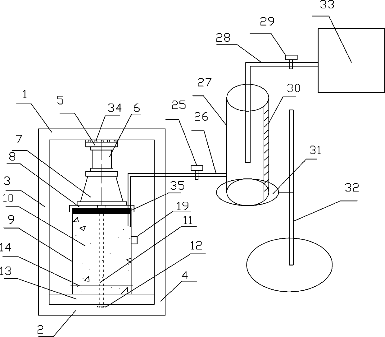
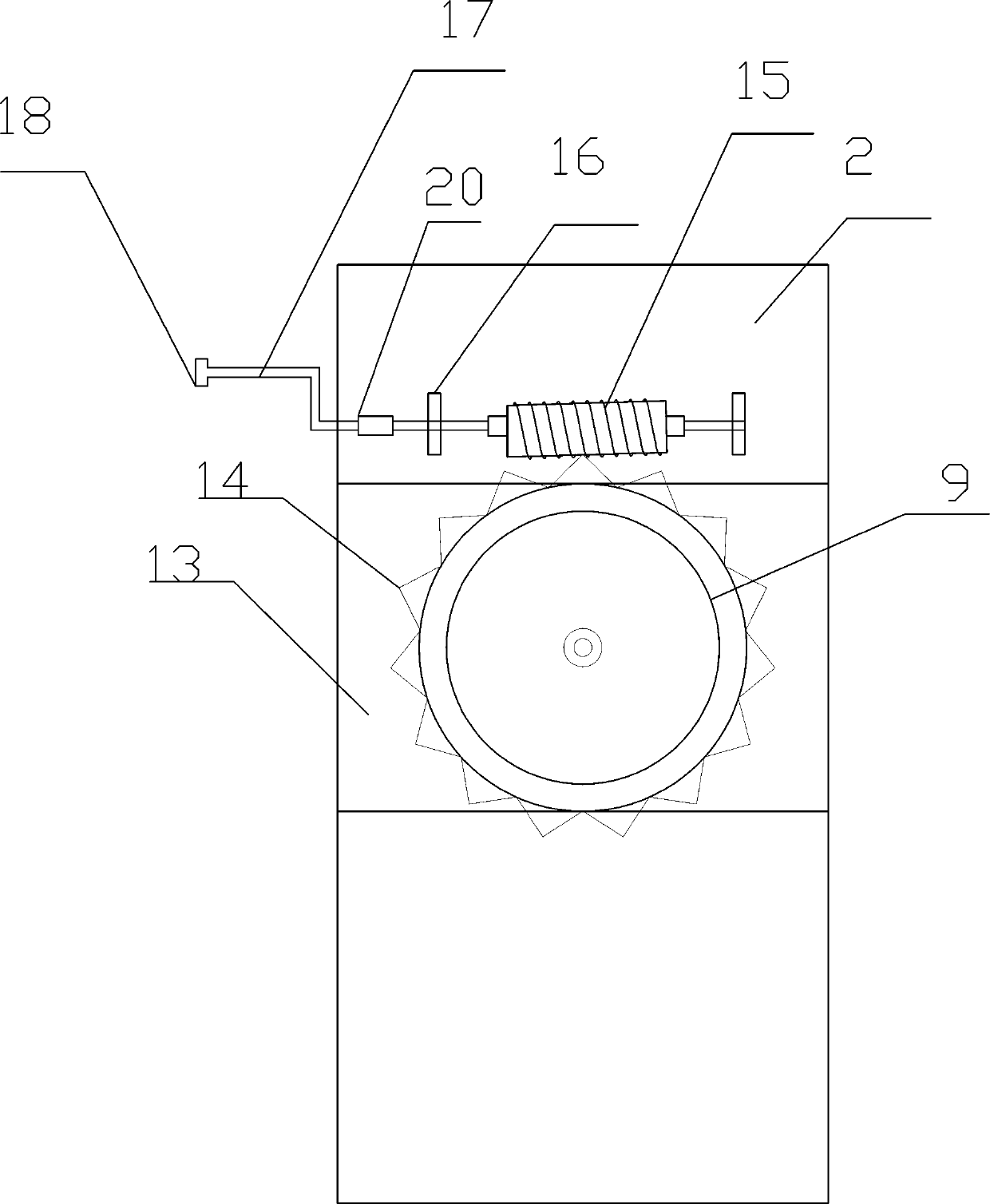
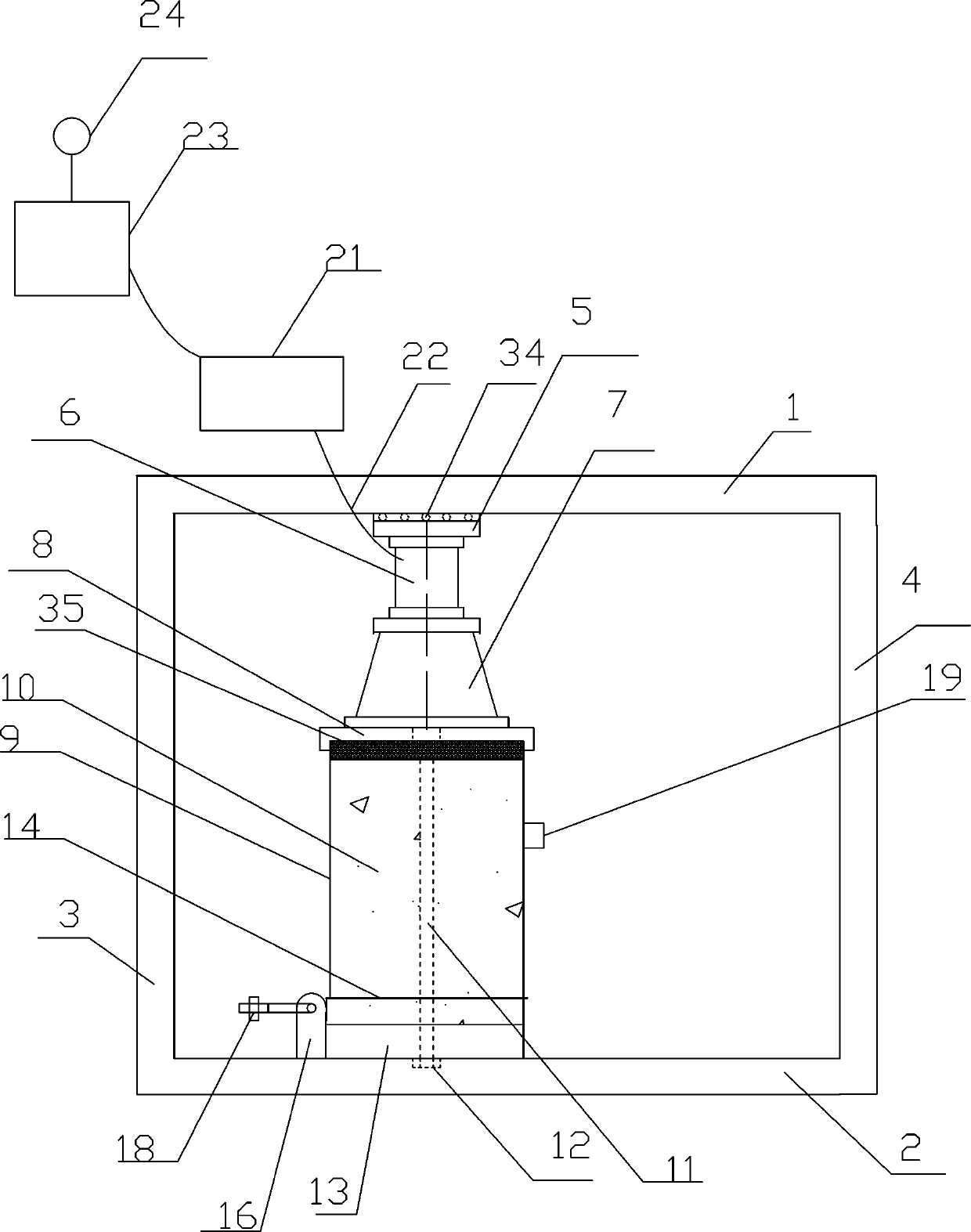
[0041] Such as Figure 1-4 As shown, a torsional shear test device for the original sample of the soil-rock interface includes a load-bearing frame, a sample fixing unit is arranged in the load-bearing frame, a normal stress loading unit is arranged above the sample fixing unit, and a lateral stress loading unit is arranged on the sample fixing unit. There is a circumferential shear unit; there is also an infiltration unit, which is used to supply water to the sample and simulate the torsional shear test of the soil-rock interface in a water-containing state.

[0042] Specifically, the bearing frame includes a top plate 1 , a bottom plate 2 , a left vertical vertical plate 3 and a right vertical vertical plate 4 , thereby forming a closed space for torsional shear tests.

[0043] The sample fixing unit includes a sleeve 9 , a sample 10 , and a rock plate 13 , wherein the sample 10 is placed in the sleeve 9 and the sleeve 9 is placed above the rock plate 13 . The rock plate 13 is


PUM


Abstract

The invention discloses a soil-rock interface original sample torsional shear test device, comprising a bearing frame in which a sample fixing unit is arranged; a normal stress loading unit is arranged above the sample fixing unit; an annular shear unit is arranged on the lateral side of the sample fixing unit; the sample fixing unit comprises a sleeve, a sample and a rock plate; the sample is placed into the sleeve that is placed on the rock plate; a fixed shaft rod at the bottom of the bearing frame penetrates through the rock plate, and the sleeve stretches into the sample; the normal stress loading unit comprises a force transferring plate, a jack, a pressure sensor and a cushion plate sequentially arranged on the sleeve; the annular shearing unit comprises a worm and gear mechanism installed on the sleeve. According to the soil-rock interface original sample torsional shear test device provided by the invention, the torsional shear test of the in-situ sample can be performed, andmeanwhile, the non-uniform distribution of the shearing stress on the shearing surface can be avoided.

Description


Claims


Application Information

Patent Timeline
Owner CHINA THREE GORGES UNIV
Why Eureka
Try Eureka