Beam processing method, base station and terminal

A processing method and beam technology, applied in the field of communication, can solve the problems of large delay and long time for communication links to restore links, and achieve the effects of reducing delay, improving user experience, and improving link recovery speed.

Active Publication Date: 2018-10-09
VIVO MOBILE COMM CO LTD
View PDF5 Cites 11 Cited by
  • Summary
  • Abstract
  • Description
  • Claims
  • Application Information

AI Technical Summary

Benefits of technology

This technology allows for better communication between two devices without having them constantly monitoring all possible transmissions on different frequencies. It uses an identification (ID) that indicates if both parties are allowed access to certain resources within their network's coverage area. When one device detects another signal while it cannot receive this detection due to poor radio reception quality, its own ID will indicate available resources with higher priority than other users who may have previously sent requests through these connections. By selecting specific ones of those connected together based upon their capabilities, they don’t waste too much power because only necessary equipment needs to work properly.

Problems solved by technology

This patented technical problem addressed in this patents relates to improving the use of massive MI-MI MO techniques in ultra wide area networks (UMNETs). Specifically, current methods require expensive components such as advanced device capabilities and complex hardware configurations due to their limited space availabilities. Additionally, there may exist issues related to reducing overhead costs associated with these processes when implementing new designs involving higher frequencies.

Method used


Image

  • Beam processing method, base station and terminal
  • Beam processing method, base station and terminal
  • Beam processing method, base station and terminal

Examples


Embodiment Construction

[0040]The following will clearly and completely describe the technical solutions in the embodiments of the present invention with reference to the accompanying drawings in the embodiments of the present invention. Obviously, the described embodiments are some of the embodiments of the present invention, but not all of them. Based on the embodiments of the present invention, all other embodiments obtained by persons of ordinary skill in the art without creative efforts fall within the protection scope of the present invention.

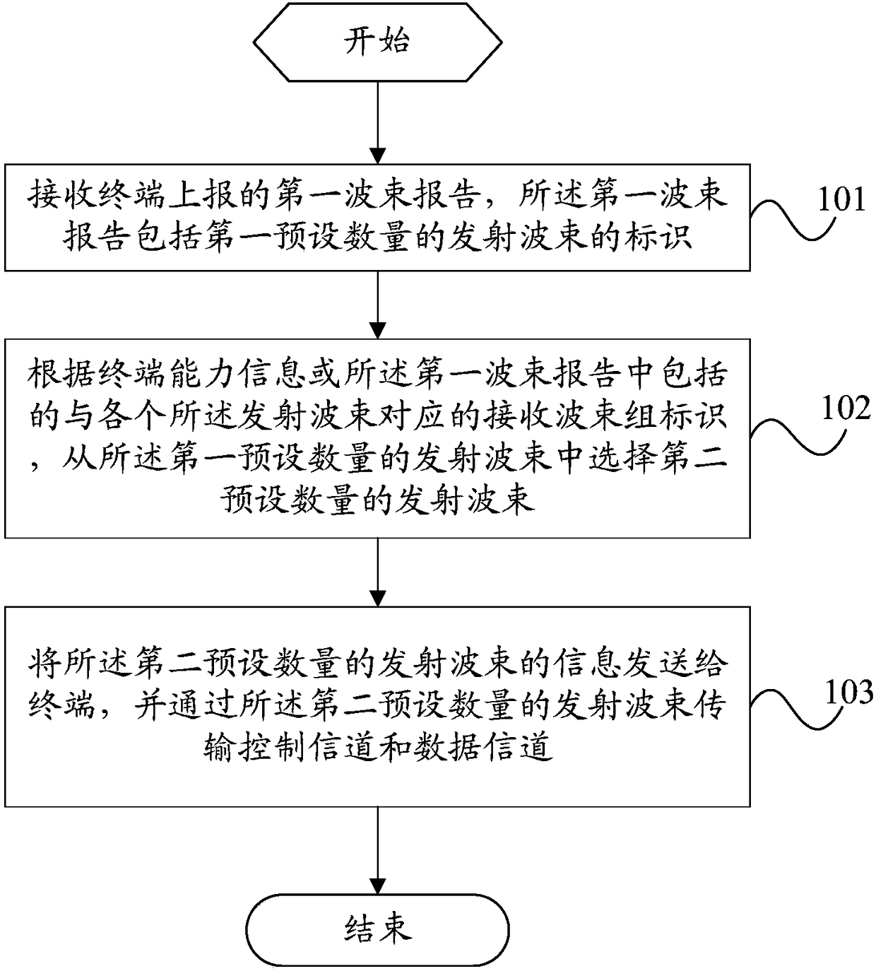
[0041] like figure 1 As shown, an embodiment of the present invention provides a beam processing method applied to a base station, including:

[0042] Step 101: Receive a first beam report reported by a terminal, where the first beam report includes identities of a first preset number of transmit beams.

[0043] In the above embodiments of the present invention, since there are many beam-to-link links between the base station and the terminal, in order to


PUM


Abstract

The invention provides a beam processing method, a base station and a terminal. The beam processing method comprise the steps of receiving a first beam report reported by the terminal, wherein the first beam report includes the identification of a first preset number of transmitting beams; selecting a second preset number of transmitting beams from the first preset number of transmitting beams according to terminal capacity information or identification of a receiving beam group which is included in the first beam report and corresponds to each of the transmitting beams, wherein both the firstpreset number and the second preset number are greater than or equal to 2; and transmitting information of the second preset number of transmitting beams to the terminal, and transmitting a control channel and a data channel through the second preset number of transmitting beams, thereby being capable of improving the link recovery speed, reducing the time delay caused by the link recovery, and improving the user experience.

Description


Claims


Application Information

Patent Timeline
Owner VIVO MOBILE COMM CO LTD
Why Eureka
Try Eureka