Paint drying device for agricultural machine part

A drying device and accessories technology, which is applied to the surface coating liquid device, pretreatment surface, coating, etc., can solve the problems of low reliability, low practicability, and poor forming effect of the paint layer on the surface of accessories. To achieve the effect of improving the reliability of use and ensuring the molding effect

Inactive Publication Date: 2018-10-30
JIANGSU ZIQIANG COATING MACHINERY
View PDF0 Cites 1 Cited by
  • Summary
  • Abstract
  • Description
  • Claims
  • Application Information

AI Technical Summary

Benefits of technology

The present invent describes an improved system for cleaning or painting industrial equipment such as crop harvesters during maintenance operations. By attaching these items onto suspended rod systems made up of several groups of suspending wires attached at their base end points, they may also have other uses like being mounted inside baskets used for storage purposes. This allows them to move freely within the machine without interferring from each others' movements. Additionally, it simplifies assembly processes compared to previous methods where all parts were individually connected together beforehand. Overall, this technology improves efficiency and reduces costs associated therewith while ensuring effective removal of coatings applied over large areas of surfaces.

Problems solved by technology

This technical problem addressed by this patented technology relates to improving the durability and performance of painted surfaces during industrial machine parts manufacturing processes such as those involving coating metal plated steel or other materials onto them. Current methods involve waiting until after each step before adding another set of equipment into the process, making it difficult if done manually without ensurely addressing any issues related to space limitations.

Method used


Image

  • Paint drying device for agricultural machine part
  • Paint drying device for agricultural machine part
  • Paint drying device for agricultural machine part

Examples


Embodiment Construction

[0021] The specific implementation manners of the present invention will be further described in detail below in conjunction with the accompanying drawings and embodiments. The following examples are used to illustrate the present invention, but are not intended to limit the scope of the present invention.

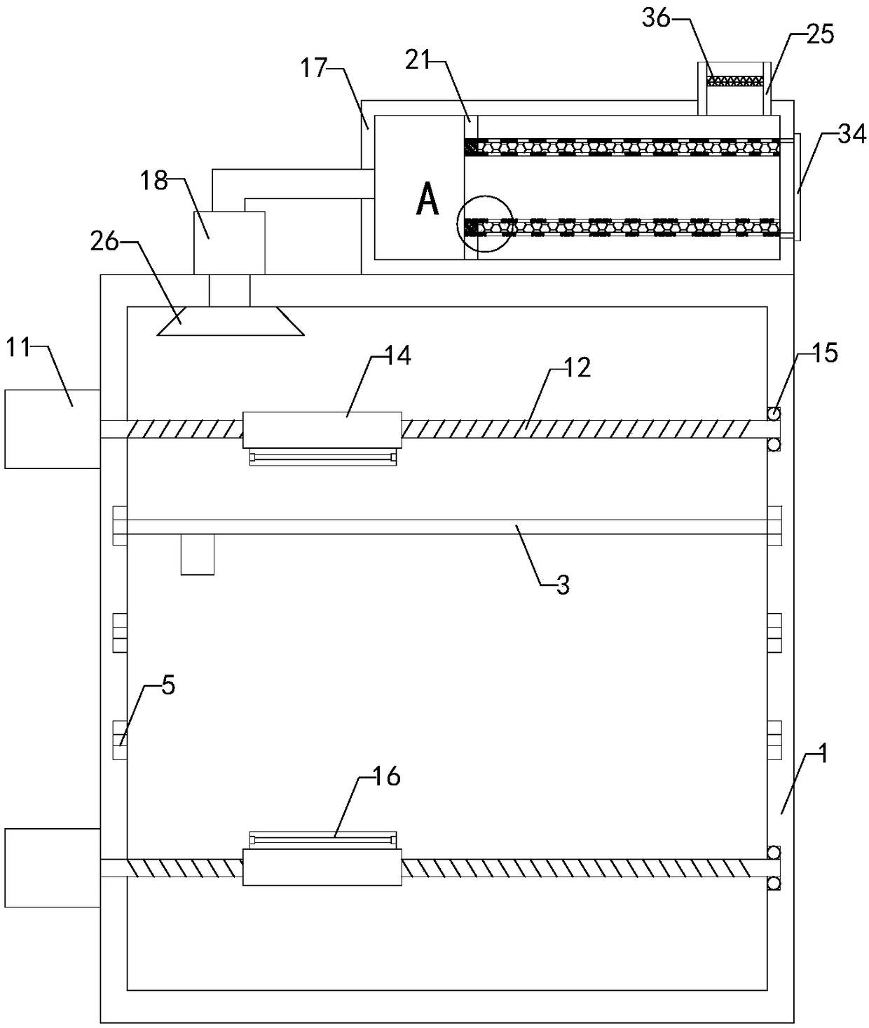
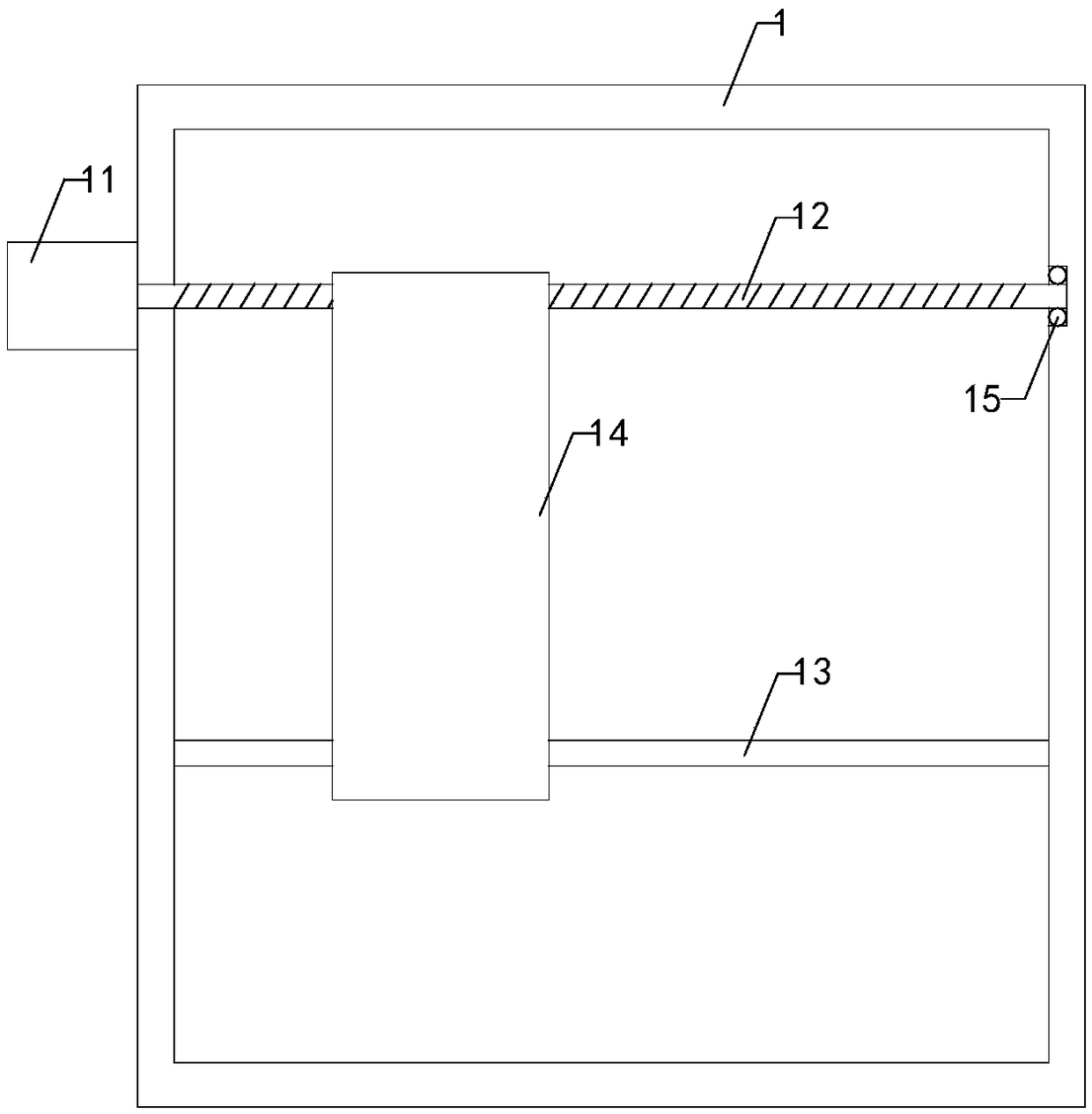
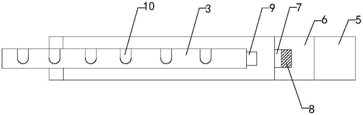
[0022] Such as Figure 1 to Figure 7As shown, a paint drying device for agricultural machinery parts of the present invention includes a drying box 1, a working cavity is arranged inside the drying box, a pick-and-place opening is provided at the front end of the drying box, and a Door panel 2, the left end of the door panel is hinged to the front left side of the drying box; it also includes a rectangular frame 3 and multiple sets of hanging rods 4, and the left side wall and the right side wall of the working chamber are respectively provided with a left chute 5 and a right side wall. chute, and in the left chute and right chute are respectively provided with a left slider


PUM


Abstract

The invention relates to the technical field of paint drying accessory devices, in particular to a paint drying device for an agricultural machine part. According to the paint drying device, the partis taken and placed conveniently, and using reliability is improved; and the forming effect of a paint layer on the surface of the part can be ensured. The paint drying device comprises a drying box,a rectangular frame, a plurality of sets of hanging rods and two sets of iron columns. A left sliding groove and a right sliding groove are formed in the left side wall and the right side wall of a working cavity correspondingly. A left sliding block and a right sliding block are arranged in the left sliding groove and the right sliding groove correspondingly. Mounting grooves are formed in the front ends of the left sliding block and the right sliding block correspondingly, and magnetic blocks are mounted in the two sets of mounting grooves correspondingly. A plurality of sets of left clamping grooves and a plurality of sets of right clamping grooves are formed in the right end of a left frame body of the rectangular frame and the left end of a right frame body of the rectangular frame correspondingly. A plurality of sets of fixing devices are arranged at the bottom ends of the multiple sets of hanging rods correspondingly. The paint drying device further comprises an upper motor, anupper lead screw, an upper limiting rod, an upper mounting plate, a lower motor, a lower lead screw, a lower limiting rod, a lower mounting plate, an upper ball bearing, a lower ball bearing and a paint baking lamp tube.

Description


Claims


Application Information

Patent Timeline
Owner JIANGSU ZIQIANG COATING MACHINERY
Why Eureka
Try Eureka