Fixed standing-wave ratio (SWR) mismatch load

A technology of mismatched load and standing wave ratio, applied in waveguide-type devices, electrical components, circuits, etc., can solve the problems of difficult debugging, low production efficiency, inconvenient use, etc., and achieve easy debugging, small structural size, flatness high effect

Inactive Publication Date: 2018-11-06
THE 41ST INST OF CHINA ELECTRONICS TECH GRP
View PDF3 Cites 2 Cited by
  • Summary
  • Abstract
  • Description
  • Claims
  • Application Information

AI Technical Summary

Problems solved by technology

[0004] Aiming at the problems of the existing fixed VSWR mismatch load in the prior art with large structural si

Method used


Image

  • Fixed standing-wave ratio (SWR) mismatch load
  • Fixed standing-wave ratio (SWR) mismatch load
  • Fixed standing-wave ratio (SWR) mismatch load

Examples


Embodiment Construction

[0020] The technical solutions of the present invention will be further described below in conjunction with the accompanying drawings in the embodiments of the present invention.

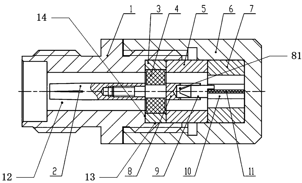
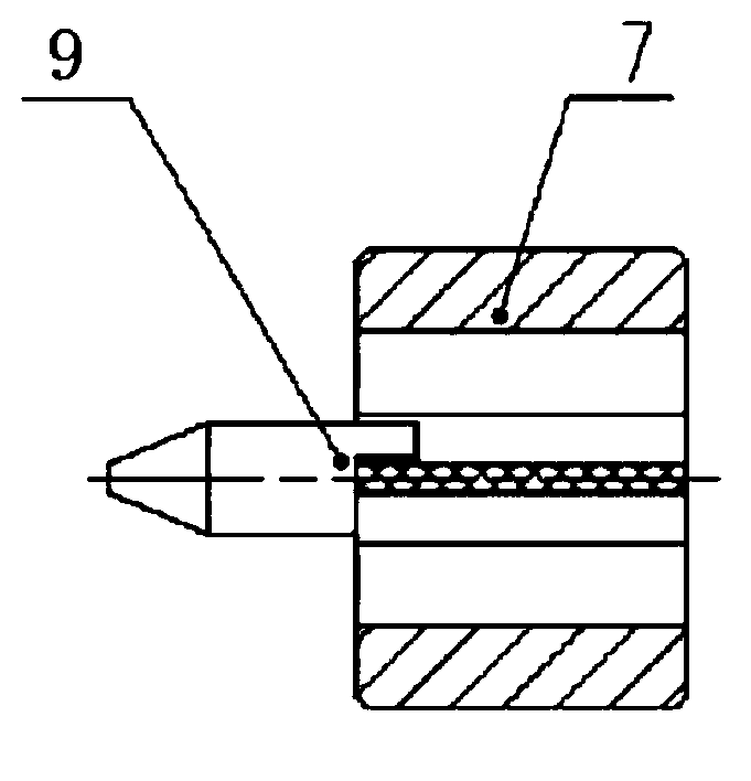
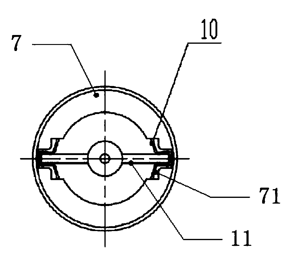
[0021] A fixed VSWR mismatch load, including an outer conductor 1, an inner conductor 8, pins 9, a microstrip sheet 11 and an end cap 6,

[0022] The outer conductor 1 is a tubular part, the inner conductor is installed and fixed in the inner hole of the outer conductor 1, and the rear end of the inner conductor is provided with a blind hole 81, and the blind hole 81 is adapted to the front end of the pin 9 , the microstrip sheet 11 is arranged at the rear end of the pin 9, the microstrip sheet 11 is fixedly installed in the end cover 6, the end cover 6 is detachably connected with the outer conductor 1, the microstrip sheet 11 The substrate is an alumina ceramic substrate covered with thin-film resistors, the dielectric constant of the alumina ceramic substrate is 9.9, and the thin-film resistor on th


PUM


Abstract

The invention discloses a fixed standing-wave ratio (SWR) mismatch load, including outer conductors, inner conductor, a microstrip sheet and an end cap, the outer conductor is a tubular part, the inner conductor is mounted and fixed in the inner hole of the outer conductor, the rear end of the inner conductor is provided with a blind hole, the blind hole is adapted to the front end of the pin, theend cap is detachably connected with the outer conductor, the substrate of the microstrip sheet is an alumina ceramic substrate, the alumina ceramic substrate is coated with a thin film resistor. Theinvention has the advantages that mismatched loads with different standing wave ratios can be obtained by changing the square resistance of the thin film resistor, the working frequency range of themismatched loads can reach DC - 50GHz, and the standing wave flatness of the mismatched loads is higher than that of the prior art. The size of the structure is small, and the length is reduced by about half compared with the mismatch load using the column resistor, which greatly reduces the size of the structure. In addition, the adjusting screw can be not used or used for debugging, so that thedebugging is easier.

Description


Claims


Application Information

Patent Timeline
Owner THE 41ST INST OF CHINA ELECTRONICS TECH GRP
Why Eureka
Try Eureka