Speed limiter of monorail conveyor

A technology of monorail conveyor and speed limiter, which is applied in the direction of mechanical equipment, brake type, drum brake, etc., can solve the problems of complex structure and poor installation flexibility, and achieve the effect of flexible installation, consistent speed limit effect and ingenious design

Active Publication Date: 2018-11-23
EAST CHINA JIAOTONG UNIVERSITY
View PDF8 Cites 4 Cited by
  • Summary
  • Abstract
  • Description
  • Claims
  • Application Information

AI Technical Summary

Benefits of technology

This new type of device for controlling movement on an endlessly moving object (such as a railroad track) uses one set of rollers instead of multiple ones at once - this allows for flexibility in mountings while still providing equal speeds between them. Additionally, by combining both front shoes and rear shoots into a single unit, there are fewer parts needed compared to traditional methods like hydraulic cylinders used alone. Overall, these technical features improve efficiency and reliability during operation over existing systems.

Problems solved by technology

This technical problem addressed by this patented describes two main issues related to setting up an efficient way for controllers on horse chains at high speeds without exceeding their maximum safe operating area. Firstly, current systems lack accurate control over how fast they run based upon factors like slope angle and roller velocity. Secondly, these conventional solutions require expensive hardware devices due to complexity associated with mounting and connecting mechanisms.

Method used


Image

  • Speed limiter of monorail conveyor
  • Speed limiter of monorail conveyor
  • Speed limiter of monorail conveyor

Examples


Embodiment Construction

[0031] The present invention will be further described below in conjunction with the examples and drawings, but the embodiments of the present invention are not limited thereto.

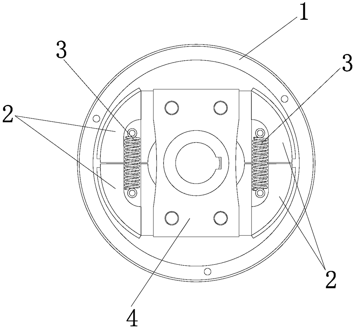
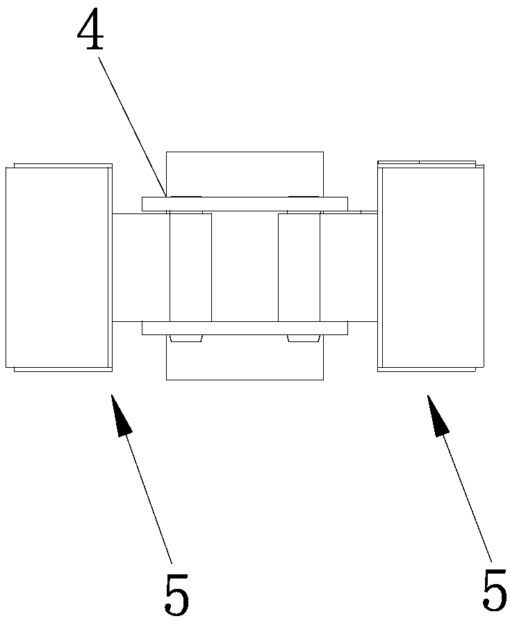
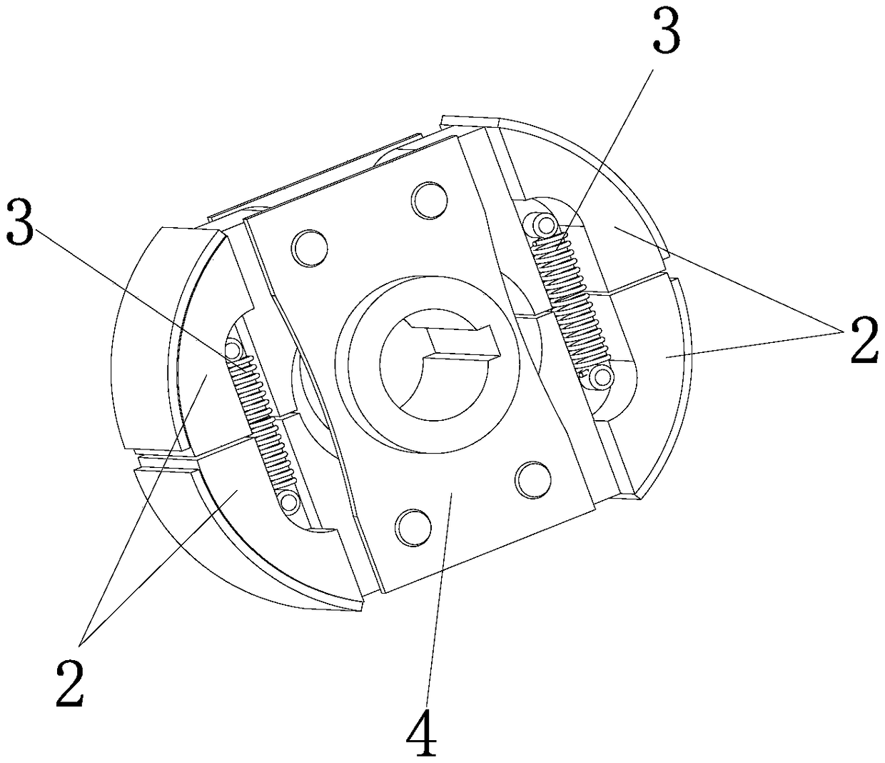
[0032] see Figure 1-Figure 10 , the speed governor of the monorail conveyor in this embodiment includes a brake drum 1 fixedly arranged on the frame and a brake mechanism arranged in the brake drum 1; wherein, the inner circular surface of the brake drum 1 is located at Outside the braking boundary circle; the braking mechanism includes a turret 4 and two groups of brake assemblies 5 arranged on the turret 4, the center of the turret 4 is connected with the running shaft of the monorail conveyor, and the two groups The moving shoes 2 are symmetrically arranged on the turret 4, and each group of brake assemblies 5 includes two brake shoes 2 and elastic elements 3; the two brake shoes 2 of each group of brake assemblies 5 are arranged symmetrically, and the two One end of each brake shoe 2 that is far a


PUM


Abstract

The invention discloses a speed limiter of a monorail conveyor. The speed limiter of the monorail conveyor comprises a brake drum and a brake mechanism, wherein the brake drum is fixedly arranged on the rack, and the brake mechanism is arranged in the brake drum; the inner circular surface of the brake drum is located outside a brake demarcation circle; the braking mechanism comprises a rotating frame and two sets of braking assemblies arranged on the rotating frame, the center of the rotating frame is connected with a running rotating shaft of the monorail conveyor, the two sets of brake shoes are symmetrically arranged on the rotating frame, and each set of braking assemblies comprises two brake shoes and an elastic element; two brake shoes of each set of brake assemblies are symmetrically arranged, and one end, far away from each other, of the two brake shoes is connected with the rotating frame in a rotating mode, and the brake shoe is always located in the brake demarcation circleunder the action of the elastic element. No matter whether the operation rotating shaft of the monorail conveyor rotates forwards or backwards is reversed, the speed limiting effect of the speed limiter of the monorail conveyor is the same, so that the device can be adapted to different types of equipment and is flexible to install.

Description


Claims


Application Information

Patent Timeline
Owner EAST CHINA JIAOTONG UNIVERSITY
Why Eureka
Try Eureka