Vortex street throttling integrated gas-liquid two-phase flowmeter and application method thereof

An all-in-one, flow meter technology, applied in the direction of detecting the dynamic effect of fluid flow, volume flow measurement device, liquid/fluid solid measurement, etc. problems, to achieve the effect of reducing the number of pipe openings and sensors, reducing the overall length, and ensuring consistency

Pending Publication Date: 2018-11-27
PETROCHINA CO LTD
View PDF1 Cites 5 Cited by
  • Summary
  • Abstract
  • Description
  • Claims
  • Application Information

AI Technical Summary

Problems solved by technology

[0002] The traditional gas field single well metering mainly adopts the gas-liquid separation metering process, the process is complicated and the investment is high
In recent years, domestic gas fields have applied various gas-liquid two-phase non-separation metering devices, which are directly used for gas-liquid two-phase metering at the wellhead of gas wells, such as a domestic patented conical orifice gas-liquid two-phase flowmeter (ZL201420671672.0), The flowmeter calculates the liquid cut-up rate by measuring the fluctu

Method used


Image

  • Vortex street throttling integrated gas-liquid two-phase flowmeter and application method thereof
  • Vortex street throttling integrated gas-liquid two-phase flowmeter and application method thereof
  • Vortex street throttling integrated gas-liquid two-phase flowmeter and application method thereof

Examples


Embodiment 1

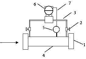
[0021] This embodiment provides a vortex throttling integrated gas-liquid two-phase flowmeter, such as figure 1 As shown (the arrow in the figure is the direction of liquid flow), it includes an intelligent differential pressure flow transmitter 6 arranged up and down and a vortex street throttling measuring device 4, and the vortex street throttling measuring device 4 includes a horizontally placed throttling pipe 8 , the two ends of the throttling pipeline 8 are respectively connected to the intelligent differential pressure flow transmitter 6 through two pressure guide tubes 3; The transmitter 5 is connected to the intelligent differential pressure flow transmitter 6 through the signal line 7;

[0022] The working principle of the vortex throttling integrated gas-liquid two-phase flowmeter is as follows:

[0023] The vortex street throttling measurement device 4 collects the vortex frequency and fluid temperature generated by the fluid passing through the throttling pipeline

Embodiment 2

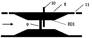
[0027] On the basis of Example 1, such as figure 2 As shown (the arrow in the figure is the direction of liquid flow), the vortex throttling measurement device 4 also includes a vortex generator 9, a vortex temperature integrated detection probe 10 for detecting vortex frequency and fluid temperature, a differential pressure gauge Hole 11; the cavity of the throttling pipe 8 is a Venturi structure, the vortex generator 9 is installed at the roar 801 in the middle of the Venturi structure, the vortex street temperature integrated detection probe 10 is located downstream of the vortex generator 9 and one end of the probe is vertical Inserted at the bellow 801, the other end is connected to the vortex temperature transmitter 5, and the differential pressure measuring hole 11 is used to connect the pressure guiding pipe 3.

[0028] Specifically, the throttling pipeline 8 is an improved Venturi structure, which is symmetrical about the central line of the waist, such as figure 2 As

Embodiment 3

[0031] On the basis of Embodiment 2, the vortex street temperature integrated detection probe 10 integrates a vortex signal detection sensor and a temperature sensor into an integrated package for detecting vortex frequency and fluid temperature.

[0032] In this embodiment, the integrated design of the vortex sensor and the temperature sensor reduces the number of pipe openings and sensors, and further simplifies the structure.


PUM


Abstract

The invention provides a vortex throttling integrated gas-liquid two-phase flowmeter and an application method thereof. The flowmeter comprises an intelligent differential pressure flow transmitter and a vortex street throttling measuring device, and the vortex street throttling measuring device is connected to the intelligent differential pressure flow transmitter through a pressure guiding tube.The vortex street throttling measuring device comprises a vortex generating body and a vortex street temperature integrated detecting probe for detecting vortex frequency and fluid temperature. The vortex generating body is installed at the shouting channel position of the vortex street throttling measuring device, and the vortex street temperature integrated detecting probe is inserted into theshouting channel position. The flowmeter integrates the structure of a throttling flowmeter and a vortex street flowmeter deeply, reduces the overall length, simplifies the structure, and makes fluidsmeasured by the vortex street flowmeter and the throttling flowmeter in the same pressure and temperature working condition system to ensure the consistency of the working condition flow rate measured by the two flowmeters and improve the density and gas-liquid flow measurement accuracy of the mixed fluids. At the same time, a vortex street sensor and a temperature sensor are integrated to reducethe number of pipe openings and sensors and further simplify the structure.

Description


Claims


Application Information

Patent Timeline
Owner PETROCHINA CO LTD
Why Eureka
Try Eureka