Electromagnetic heating system, IGBT driving control circuit and fault detection method thereof

A technology for driving control circuits and heating systems, applied in the direction of induction heating control, electric/magnetic/electromagnetic heating, electric heating devices, etc., can solve problems such as failure, IGBT breakdown failure function, noise, etc., to prevent damage or generate noise Effect

Active Publication Date: 2018-12-07
FOSHAN SHUNDE MIDEA ELECTRICAL HEATING APPLIANCES MFG CO LTD
View PDF8 Cites 0 Cited by
  • Summary
  • Abstract
  • Description
  • Claims
  • Application Information

AI Technical Summary

Problems solved by technology

Among them, the IGBT driving circuit has the driving voltage in the saturation region and the driving voltage in the amplification region. When any of

Method used


Image

  • Electromagnetic heating system, IGBT driving control circuit and fault detection method thereof
  • Electromagnetic heating system, IGBT driving control circuit and fault detection method thereof
  • Electromagnetic heating system, IGBT driving control circuit and fault detection method thereof

Examples


Embodiment Construction

[0023] Embodiments of the present invention are described in detail below, examples of which are shown in the drawings, wherein the same or similar reference numerals designate the same or similar elements or elements having the same or similar functions throughout. The embodiments described below by referring to the figures are exemplary and are intended to explain the present invention and should not be construed as limiting the present invention.

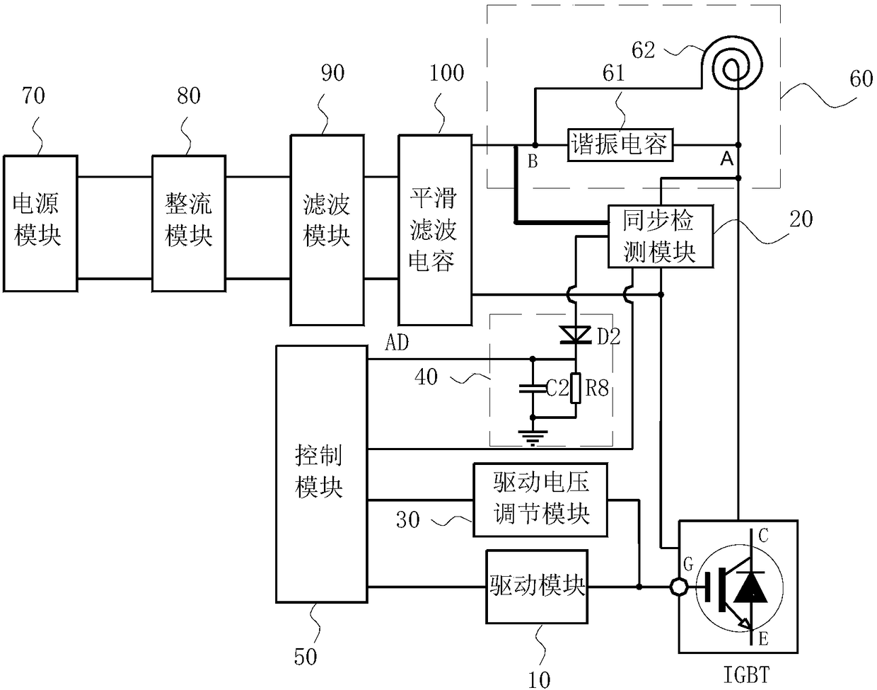
[0024]The driving control circuit of the IGBT in the electromagnetic heating system, the electromagnetic heating system and the fault detection method of the driving circuit of the IGBT in the electromagnetic heating system according to the embodiments of the present invention are described below with reference to the accompanying drawings.

[0025] In an embodiment of the present invention, the electromagnetic heating system may be an electromagnetic heating product such as an electromagnetic cooker, an electromagnetic rice cooker,


PUM


Abstract

The invention discloses an electromagnetic heating system, an IGBT driving control circuit and a fault detection method thereof. The driving control circuit comprises a driving module, a synchronous detecting module, a driving voltage regulating module, a resonant voltage detecting module and a control module. When the driving module outputs an amplification region driving voltage, the control module samples a resonant voltage detected by means of the resonant voltage detecting module when the synchronous detecting module detects at least two synchronous detection signals continuously, so as to obtain a first resonant voltage sampled value and the width of a current control pulse. When the driving module outputs a saturation region driving voltage, the control module outputs the control pulse of the current width, and samples the detected resonant voltage to obtain a second resonant voltage sampled value after continuously outputting at least two control pulses, and determines whethera driving voltage regulation branch circuit fails according to the first resonant voltage sampled value and the second resonant voltage sampled value, thereby effectively determining whether the driving voltage is faulty.

Description


Claims


Application Information

Patent Timeline
Owner FOSHAN SHUNDE MIDEA ELECTRICAL HEATING APPLIANCES MFG CO LTD
Why Eureka
Try Eureka