Control circuit and LCD module and LCD using the same

a control circuit and liquid crystal display technology, applied in the field of liquid crystal display, can solve the problems of color deviation deterioration of the display effect of the liquid crystal panel,

Active Publication Date: 2013-02-14
SHENZHEN CHINA STAR OPTOELECTRONICS TECH CO LTD
View PDF4 Cites 2 Cited by
  • Summary
  • Abstract
  • Description
  • Claims
  • Application Information

AI Technical Summary

Benefits of technology

This patent describes a device called a sliding rheostat that can be used in electronic devices like LCDs (Liquid Crystals Display). It consists of three parts: a controller, a power supply, and a liquid crystal panel. These components are placed next to each other on top of one another. A special type of signal called a digital pulse or analogue signal is sent through this system. By sending different types of signals at certain times, it becomes possible to change the voltage applied by the liquid crystal panel.

Problems solved by technology

The technical problem addressed in this patent is how to prevent voltage drops caused by differences in the lengths of wires in an LCD display due to variations in impedance between these wires.

Method used


Image

  • Control circuit and LCD module and LCD using the same
  • Control circuit and LCD module and LCD using the same
  • Control circuit and LCD module and LCD using the same

Examples


Embodiment Construction

[0021]The disclosure is illustrated by way of example and not by way of limitation in the figures of the accompanying drawings in which like references indicate similar elements. It should be noted that references to “an” or “one” embodiment is this disclosure are not necessarily to the same embodiment, and such references mean at least one.

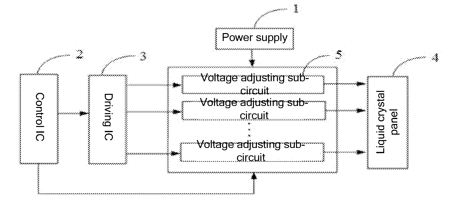
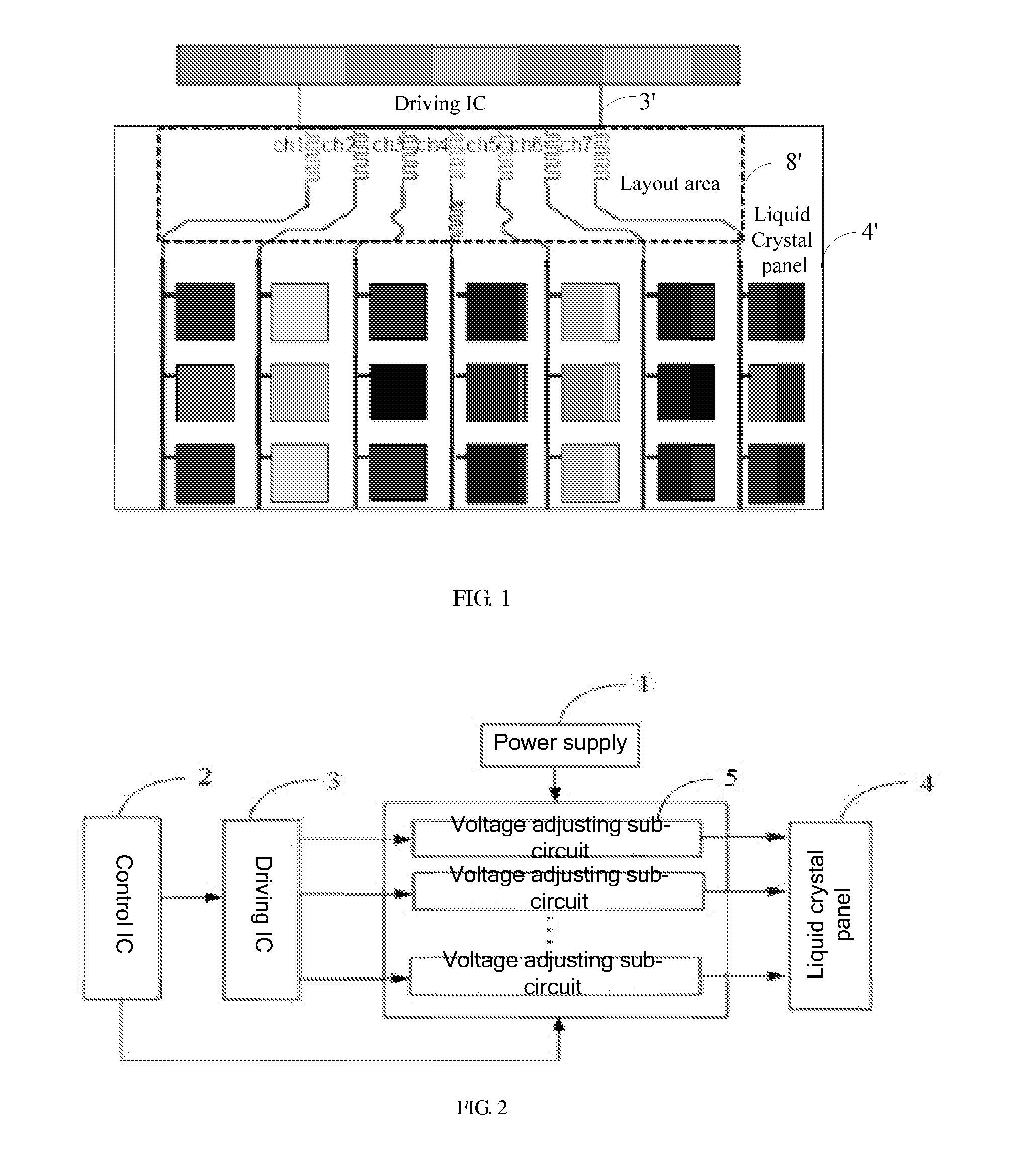
[0022]Referring to FIG. 2, a control circuit for supplying a number of driving voltages in an embodiment includes a power supply 1, a control integrated chip (IC) 2, a driving integrated chip (IC) 3, a liquid crystal panel 4, and a number of voltage adjusting sub-circuits 5. The driving IC 3 is connected to the control IC 2. Each of the voltage adjusting sub-circuits 5 is connected to the driving IC 3, the power supply 1, and the control IC 2. The liquid crystal panel 4 is connected to the voltage adjusting sub-circuits 5.

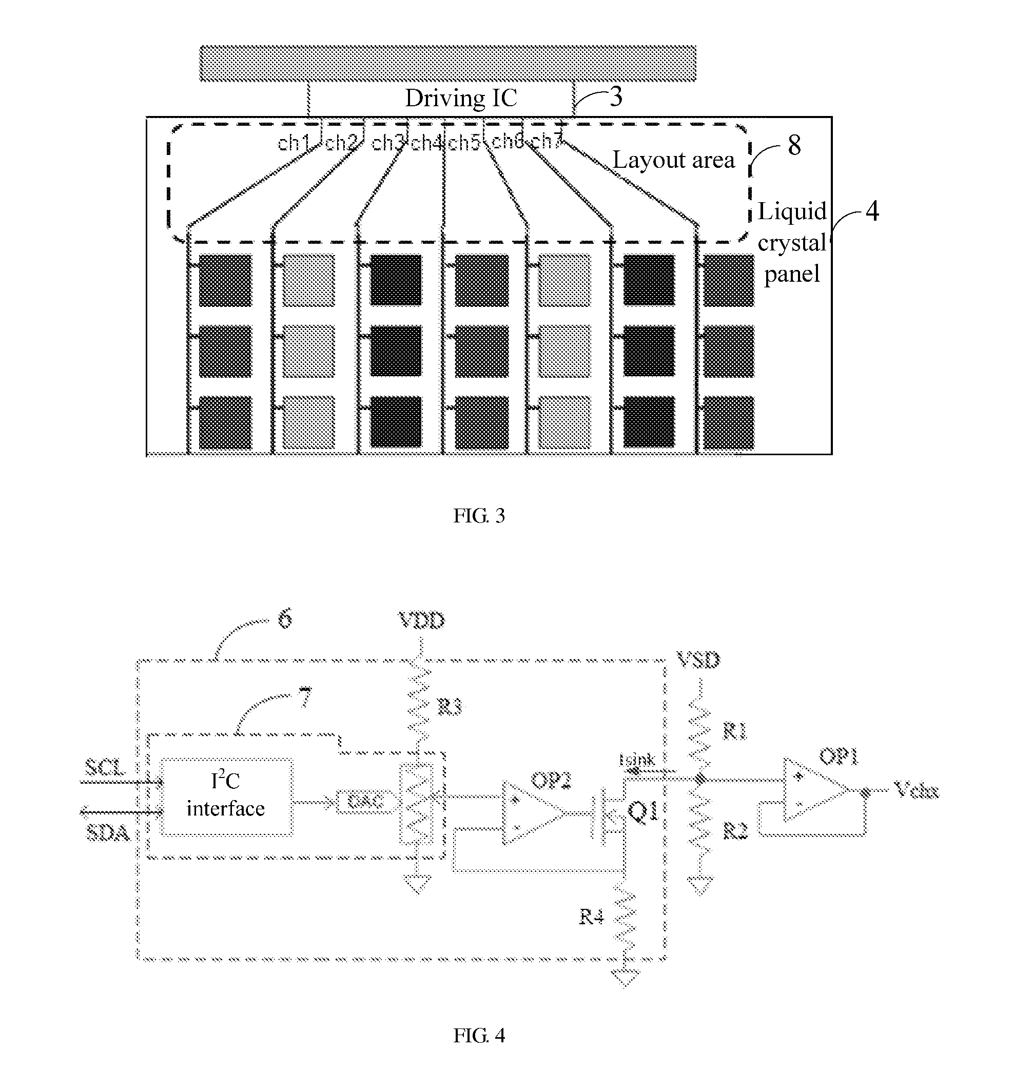
[0023]The driving IC 3 includes a number of output ports for respectively outputting a number of driving voltages. As shown in FI


PUM


Abstract

A control circuit includes a power supply, a control IC, a liquid crystal panel, a driving integrated chip arranged between the control IC and the liquid crystal panel, and a number of voltage adjusting sub-circuits. The driving integrated chip includes a plurality of output ports for outputting a plurality of driving voltages respectively. Each voltage adjusting sub-circuit is arranged between the corresponding output port of the driving integrated chip and the liquid crystal panel for adjusting an initial value the voltage outputted from the corresponding output port before the driving voltage is transferred to the liquid crystal panel. With the voltage adjusting sub-circuits, the driving voltages received by the liquid crystal panel have the same value to avoid the color deviation of the images displayed in the liquid crystal panel. This improves the display effect of the liquid crystal panel under without increasing the layout area.

Description


Claims


Application Information

Patent Timeline
Owner SHENZHEN CHINA STAR OPTOELECTRONICS TECH CO LTD
Why Eureka
Try Eureka