A transformer respirator with automatic dehumidification function

A respirator and transformer technology, applied in the direction of transformer/inductor cooling, transformer/inductor components, electrical component structure association, etc., can solve the problems of potential safety hazards, difficult management, and scrapping of respirator in transformers.

Pending Publication Date: 2018-12-14
HUBEI UNIV OF SCI & TECH
View PDF1 Cites 0 Cited by
  • Summary
  • Abstract
  • Description
  • Claims
  • Application Information

AI Technical Summary

Problems solved by technology

[0004] 1. When the silica gel used to store moisture reaches a certain amount, its water absorption effect gradually weakens until it disappears, and the staff needs to replace the silica gel. Ideally, the replaced silica gel needs to be dried and used here. However, due to disassembly The labor cost is relatively large, and the performance of silica gel is reduced after use. Under comprehensive consideration, it is generally not used again, resulting in a low utilization rate of silica gel and high use and maintenance costs;
[0005] 2. Under different environments, different regions, and different climate conditions, the cycle of silica gel reaching the replacement conditions is different, which makes management difficult and poses a safety hazard to the transformer;
[0006] 3. Although the overall structure of the respirator is simple, there are not many disassembly and assembly procedures. However, due to the high requirements of the respirator on sealing, the aging and rust of the connecting parts, and the fact that the transformer is generally located at a higher position from the ground , so that there are not many disassembly and assembly procedures for the respirator, but the disassembly and assembly requirements are extremely high, and the disassembly and assembly workers are time-consuming and laborious, which often results in the overall scrapping of the respirator;
[0007] 4. Respirators play a very critical role in wet transformers. However, due to the many management, technical and maintenance problems of respirators, there are certain safety hazards in the application of wet transformers, especially for remote mountainous areas, etc.

Method used


Image

  • A transformer respirator with automatic dehumidification function
  • A transformer respirator with automatic dehumidification function
  • A transformer respirator with automatic dehumidification function

Examples


Example Embodiment

[0040] The following are specific embodiments of the present invention combined with the accompanying drawings to further describe the technical solutions of the present invention, but the present invention is not limited to these embodiments.

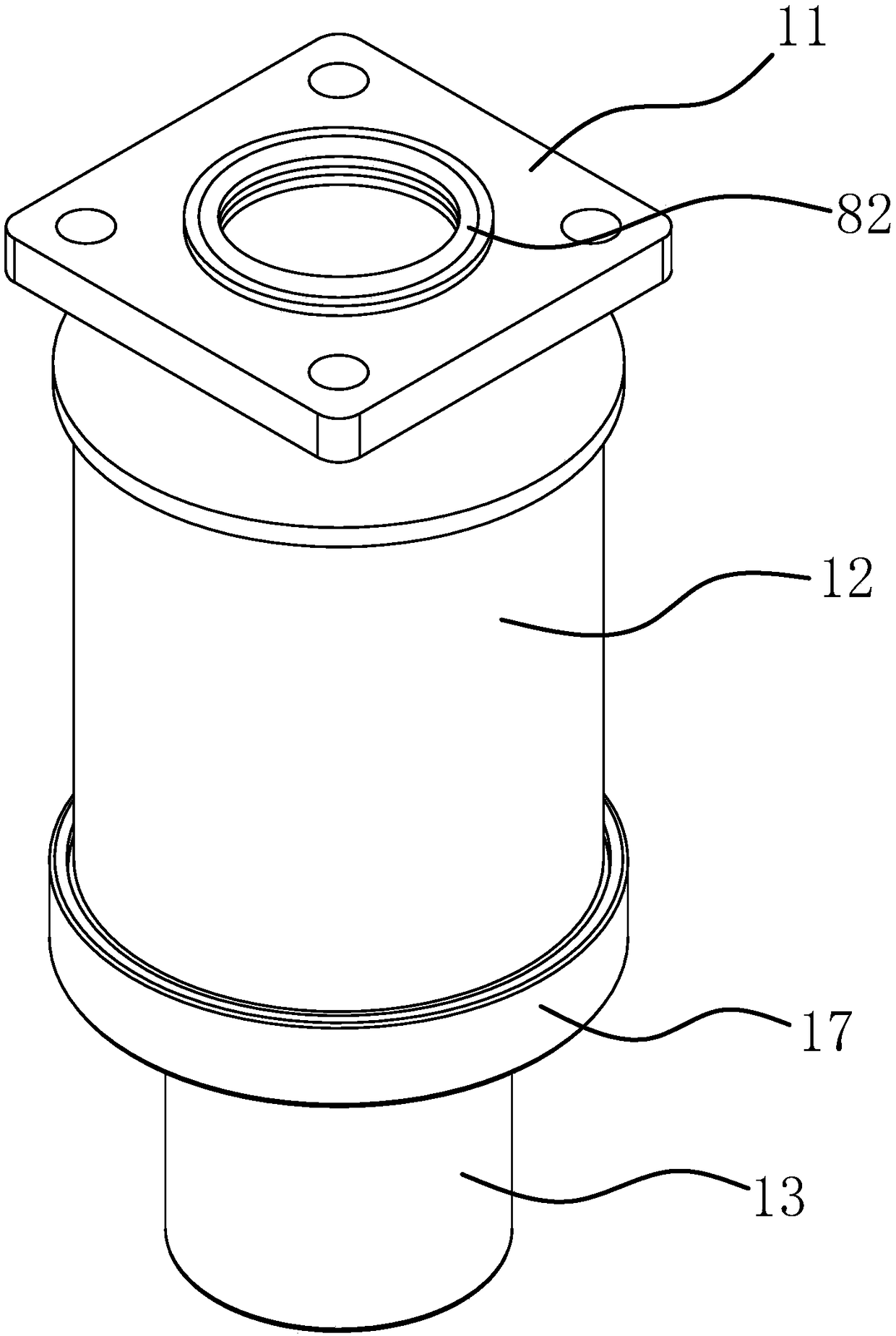
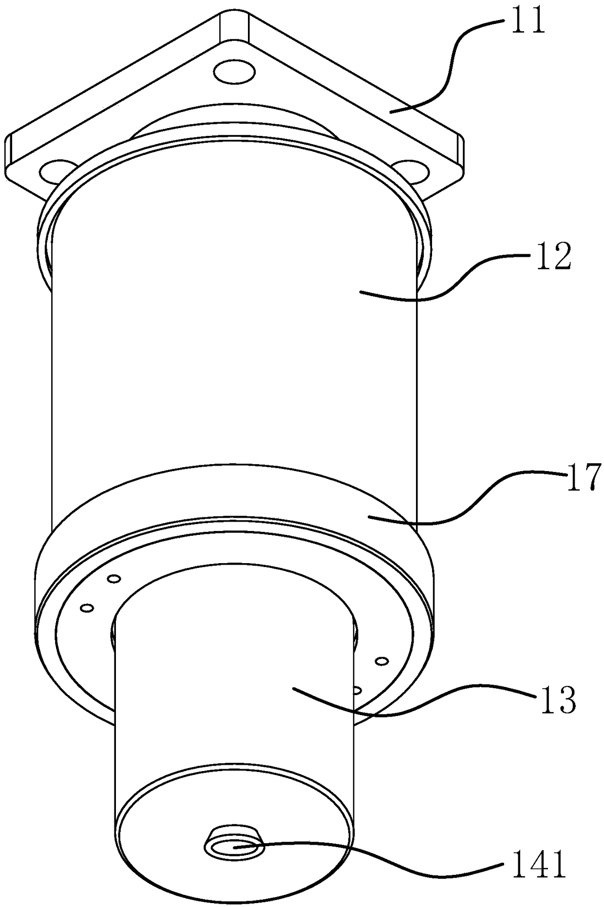
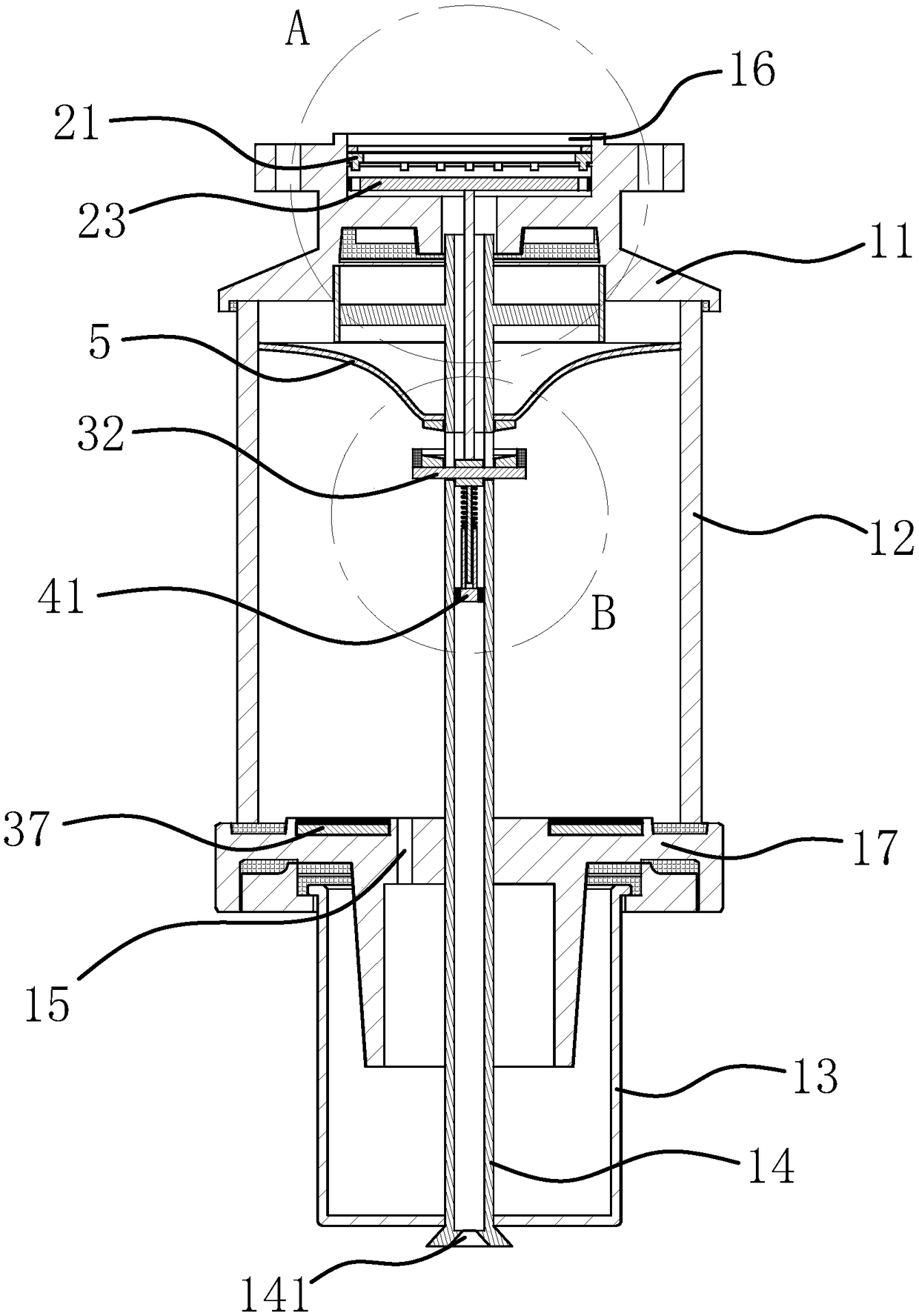
[0041] Such as figure 1 , figure 2 , image 3 , Figure 4 with Figure 5 As shown, the respirator includes a connecting flange 11, a silicone cover 12, an oil cup 13, and a breathing tube 14. The upper and lower ends of the breathing tube 14 are connected to the connecting flange 11 and the oil cup 13, respectively, and the upper end of the silicone cover 12 is connected to The flanges 11 are sealed and connected, the lower end of the silicone cover 12 is connected to the oil cup 13 through a mounting seat 17, and the mounting seat 17 is sealed to the oil cup 13 and the silicone cover 12; the mounting seat 17 is provided with a communicating oil cup 13 And the oil through hole 15 in the inner cavity of the silicone cover 12; the silicone cov


PUM


Abstract

The invention provides a transformer respirator with an automatic dehumidification function, and belongs to the technical field of electrical equipment. The respirator includes a connecting flange, asilica gel cover, an oil cup and a breathing tube, the upper and lower ends of the breathing tube are respectively connected with the connecting flange and the oil cup, the breathing tube is providedwith a through groove passing through the radial line of the breathing tube, a sliding block capable of sliding longitudinally in the through groove is transverly inserted in the through groove, an iron attraction block is arranged on the outer edge of the upper surface of the sliding block, an armature block corresponding to the iron attraction block is arranged on the breathing tube, and an energizing coil is wound on the armature block; a first plug and a second plug can block the breathing tube located above the sliding block and the breathing tube located below the sliding block, respectively; and a heating plate is arranged on a mounting base and the energizing coil are connected with a power supply, a humidity sensor is arranged in the silica gel cover, the humidity sensor is connected with a controller, and the controller is connected with the heating plate and the energizing coil. The transformer respirator with an automatic dehumidification function provided by the inventionhas the advantage of being capable of automatically dehumidifying the respirator.

Description


Claims


Application Information

Patent Timeline
Owner HUBEI UNIV OF SCI & TECH
Why Eureka
Try Eureka