Error compensation method for bias temperature of fiber optical gyroscope

A technology of temperature error and fiber optic gyroscope, applied in the field of fiber optic inertia, can solve the problems of low precision of fiber optic gyroscope, inability to effectively compensate the temperature error of fiber optic gyroscope, and inability to reflect the temperature change of the fiber optic ring, and achieve the effect of improving accuracy

Inactive Publication Date: 2018-12-28
HUNAN AEROSPACE ELECTROMECHANICAL EQUIP & SPECIAL MATERIAL INST
View PDF1 Cites 8 Cited by
  • Summary
  • Abstract
  • Description
  • Claims
  • Application Information

AI Technical Summary

Problems solved by technology

However, in the second method, generally only the temperature of one point in the fiber optic gyroscope is used as the compensation factor, which cannot reflect the temperature ch

Method used


Image

  • Error compensation method for bias temperature of fiber optical gyroscope
  • Error compensation method for bias temperature of fiber optical gyroscope
  • Error compensation method for bias temperature of fiber optical gyroscope

Examples


Embodiment Construction

[0022] The method for compensating the zero bias temperature error of the fiber optic gyroscope includes the following steps:

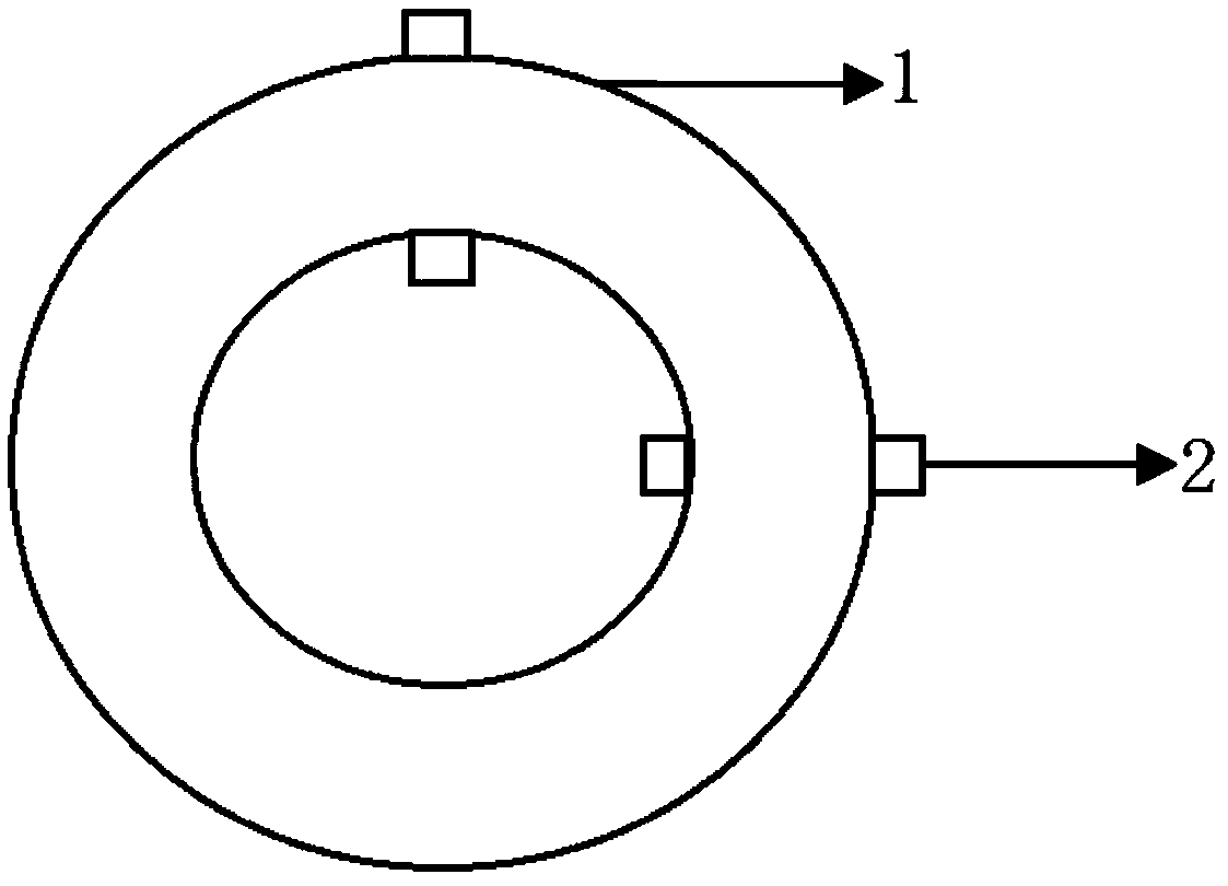
[0023] Step A. Attach N temperature sensors 2 on the fiber ring 1 of the fiber optic gyroscope, wherein at least one temperature sensor 2 is attached to the inside of the fiber ring 1, and at least one temperature sensor 2 is attached to the outside of the fiber ring 1; 2≤N ≤5. When N is an even number, the temperature sensors 2 attached to the inner side of the optical fiber ring 1 and the outer side of the optical fiber ring 1 correspond to each other in spatial position. When N is an odd number, there is a one-to-one correspondence between the attachment of N−1 temperature sensors 2 on the inside and outside of the optical fiber ring 1 .

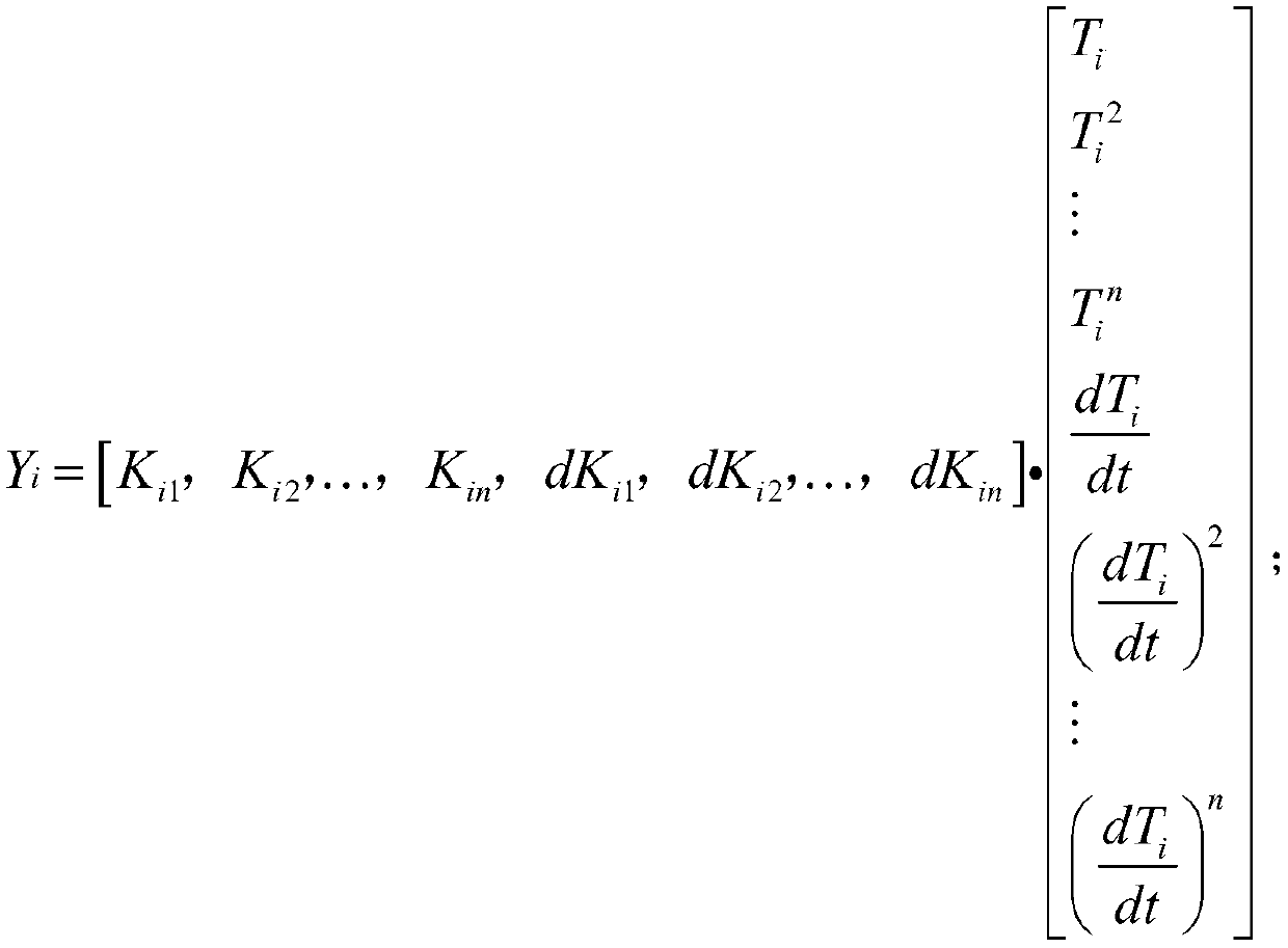
[0024] Step B. Establish the temperature error model of the fiber optic gyroscope:

[0025] in,

[0026]

[0027] K i1 ~K in 、dK i1 ~dK in is the coefficient of each temperature item corresponding to the


PUM


Abstract

The invention discloses an error compensation method for a bias temperature of a fiber optic gyroscope, comprising the following steps of: A. attaching N temperature sensors on a fiber coil of the fiber optic gyroscope, wherein at least one temperature sensor is attached to the inner side of the fiber coil, and at least one temperature sensor is attached to the outer side of the fiber coil; and Nis greater than or equal to 2; B. establishing a temperature error model of the fiber optic gyroscope as shown in the description; C. carrying out temperature error compensation on the fiber optic gyroscope according to the temperature error model. According to the error compensation method for the bias temperature of the fiber optic gyroscope, the temperature error of the fiber optic gyroscope iscompensated based on a multi-point temperature, the situation that the fiber coil is affected by the temperature effect can be fully reflected, the bias temperature drift condition of the fiber opticgyroscope is compensated more effectively, and the precision of the fiber optic gyroscope is effectively improved.

Description


Claims


Application Information

Patent Timeline
Owner HUNAN AEROSPACE ELECTROMECHANICAL EQUIP & SPECIAL MATERIAL INST
Why Eureka
Try Eureka