Turnover device for mechanical automatic machining

A flipping device and mechanical technology, applied in positioning devices, metal processing equipment, metal processing machinery parts, etc., can solve problems affecting the quality of sheet metal processing, and achieve the effect of preventing serious deformation

Pending Publication Date: 2019-01-04
QUANZHOU MIAOYI AUTOMATION MACHINERY CO LTD
View PDF0 Cites 22 Cited by
  • Summary
  • Abstract
  • Description
  • Claims
  • Application Information

AI Technical Summary

Problems solved by technology

[0003] The purpose of the present invention is to solve the problems in the prior art that affe

Method used


Image

  • Turnover device for mechanical automatic machining
  • Turnover device for mechanical automatic machining

Examples


Embodiment Construction

[0018] The following will clearly and completely describe the technical solutions in the embodiments of the present invention with reference to the accompanying drawings in the embodiments of the present invention. Obviously, the described embodiments are only some, not all, embodiments of the present invention.

[0019] In describing the present invention, it should be understood that the terms "upper", "lower", "front", "rear", "left", "right", "top", "bottom", "inner", " The orientation or positional relationship indicated by "outside", etc. is based on the orientation or positional relationship shown in the drawings, and is only for the convenience of describing the present invention and simplifying the description, rather than indicating or implying that the referred device or element must have a specific orientation, so as to Specific orientation configurations and operations, therefore, are not to be construed as limitations on the invention.

[0020] refer to Figure 1-2


PUM


Abstract

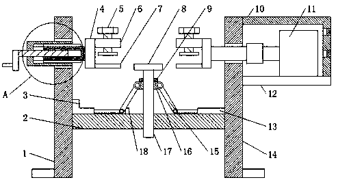
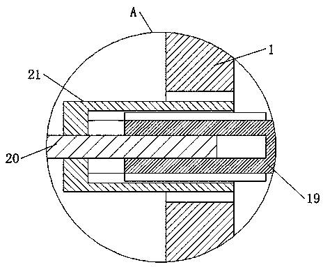
The invention discloses a turnover device for mechanical automatic machining. The turnover device comprises a first support plate and a second support plate, wherein the first support plate corresponds to the second support plate, corresponding through holes are respectively formed in the same high position of the first support plate and the second support plate, bearings are fixedly connected tothe inner walls of the two through holes, two symmetrical fixtures are arranged between the first support plate and the second support plate, one fixture is connected with the first support plate by virtue of an adjusting mechanism, a rotating rod is fixedly connected to the center of one side, which is far from the first support plate, of the other fixture, the rotating rod penetrates through thebearing on the second support plate and is rotatably connected with the second support plate, a mounting plate is fixedly connected to one side, which is far from the first support plate, of the second support plate, a motor is fixedly connected to the top of the mounting plate, and the tail end of an output shaft of the motor is fixedly connected with one end, which is far from the fixture, of the rotating rod by virtue of a coupling. According to the turnover device, the purpose of no deformation when a plate is milled is realized by utilizing the lifting support plates.

Description


Claims


Application Information

Patent Timeline
Owner QUANZHOU MIAOYI AUTOMATION MACHINERY CO LTD
Why Eureka
Try Eureka