Combined-cabinet

A combined cabinet and side panel technology, which is applied to cabinets, detachable cabinets, door leaves, etc., can solve the problems of single design structure, complex design of combined cabinets, monotonous forms, etc., and achieves simplified production process, easy disassembly, and remarkable technology effect of effect

Pending Publication Date: 2019-01-11
广东胜意塑胶有限公司
View PDF0 Cites 4 Cited by
  • Summary
  • Abstract
  • Description
  • Claims
  • Application Information

AI Technical Summary

Benefits of technology

The combination cupboard described by this patented technology allows for easy assembly or reconfiguration based on user requirements without complicated structures that are difficult to produce. It also includes features like rotation between panels and locking mechanisms, making it easier than previous designs due to its simplified structure.

Problems solved by technology

This patented technical solution described by this patents involves making up an entire new type of furniture that has two parts: a main part with locked doors on top; another smaller door called a subpart where only certain keys needed inside them have been put into use during assembly. However, these existing designs may make it hard to move around due to their size and weight.

Method used


Image

  • Combined-cabinet
  • Combined-cabinet
  • Combined-cabinet

Examples


Embodiment 1

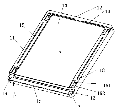
[0070] like Figure 1-25 The combination cabinet shown includes a middle panel 1 , a rear panel 2 , a side panel 3 , a top panel 4 and a door panel 5 .

[0071] The middle plate 1 includes a middle plate body 10, a middle plate side 11 and a middle plate rear 12 arranged around the middle plate body 10, the middle plate side 11 is divided into a middle plate left side and a middle plate right side, and the middle plate The height of the board body 10 is lower than that of the sides 11 of the middle board and the rear side 12 of the middle board. The middle board body 10 is used to separate the storage space and can be used to carry objects to be stored.

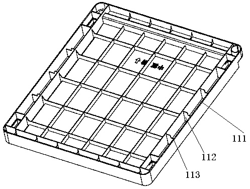
[0072] The middle board 1 is divided into front and back, the front is as follows figure 1 As shown, the back as figure 2 As shown, a first boss 13 is provided on the right side of the front end of the middle plate 1, and a first installation part 15 is provided on the first boss 13, and the first installation part 15 may pre

Embodiment 2

[0098] In this embodiment, the door panel is improved on the basis of Embodiment 1, and a layer panel 5 is added.

[0099] like Figure 13 , 14 As shown, the combination cabinet also includes a layer board 6, and the structure of the layer plate 6 is the same as that of the middle plate in Example 1, except that the first boss 13 and the second boss are subtracted from the plate in Example 1. Features of the table 14 , the first mounting portion 15 , the middle plate positioning portion 16 , and the connecting bar 17 .

[0100] Specifically, the laminate 6 includes a laminate body 60, a laminate side 61 and a laminate rear 62 arranged around the laminate body 60, and the laminate side 61 is divided into a left side of the laminate and a right side of the laminate On the side, the height of the board body 60 is lower than the height of the side edge 61 of the board and the height of the rear edge 62 of the board. The board body 60 is arranged between the upper and lower side boa

Embodiment 3

[0111] This embodiment improves the laminate on the basis of Embodiment 2.

[0112] like Figure 15 , 16 As shown, the laminate of this embodiment is based on Embodiment 2, except that the laminate body 60 is removed, so that the side 61 of the laminate and the rear edge 62 of the laminate form a U-shaped structure.

[0113] This structural arrangement can connect the multi-layer space between the middle plate 1 and the top plate up and down, so as to form a space long enough to meet the needs of different objects.


PUM


Abstract

The invention relates to a combined cabinet, comprising a middle plate, a back plate, a side plate, a top plate and a door plate. The middle plate comprises a side edge of the middle plate and a backedge of the middle plate. The side edge of the middle plate is connected with the side plate. The back edge of the middle plate is connected with the back plate. A low edge of the rear plate is connected with a rear edge of the middle plate; a low edge of the side plate is connected with a side edge of the middle plate; the lower side of the rear side of the top plate is connected with the upper side of the rear plate, and the lower side of the side edge of the top plate is connected with the upper side of the side plate, and the front side of the top plate protrudes from the side plate; a second mounting part is arranged at the front end of the top plate, and the second mounting part corresponds to the position of the first mounting part; the door panel comprises a door body and a door panel fixing strip; a door panel mounting portion is arranged on the door panel fixing strip, the door panel mounting portion corresponds to the first mounting portion and the second mounting portion, the door panel mounting portion on the door panel fixing strip on the upper side of the door panel is rotatably connected with the second mounting portion of the top pane; and the door panel mounting portion on the door panel fixing strip on the lower side of the door panel is rotatably connected with the first mounting portion of the middle panel. The combined cabinet has the advantages of simplestructure, easy disassembly and remarkable progress.

Description


Claims


Application Information

Patent Timeline
Owner 广东胜意塑胶有限公司
Why Eureka
Try Eureka