A multi-terminal flexible DC network longitudinal protection method and system based on current limiting inductor voltage polarity

A current-limiting inductance and voltage polarity technology, which is applied in the direction of power transmission AC network, emergency protection circuit device, information technology support system, etc., can solve the difficulty of implementing additional protection methods, high sensitivity and reliability, and no easy implementation, etc. problem, to achieve the effect of shortening the protection time, simple principle and algorithm, and easy engineering implementation

Active Publication Date: 2019-01-15
SHANDONG UNIV +2
View PDF5 Cites 12 Cited by
  • Summary
  • Abstract
  • Description
  • Claims
  • Application Information

AI Technical Summary

Benefits of technology

This new protective system uses an induction coil that detects changes caused by electrical arcs (electricity). It doesn't have complicated algorithms but works very well when only one side needs to fail. Its technical effect is improved safety during power transmission lines due to its ability to accurately identify any potential damage from electric arc flashes without requiring complex calculations.

Problems solved by technology

The technical problem addressed in this patented technology relating to protecting multiple terminal flexibility type DC grids involves developing efficient and reliable ways to detect and isolate faulty sections within these networks without affecting other parts of the network's equipment.

Method used


Image

  • A multi-terminal flexible DC network longitudinal protection method and system based on current limiting inductor voltage polarity
  • A multi-terminal flexible DC network longitudinal protection method and system based on current limiting inductor voltage polarity
  • A multi-terminal flexible DC network longitudinal protection method and system based on current limiting inductor voltage polarity

Examples


Embodiment 1

[0045] In some implementations, a method for longitudinal protection of DC lines in a multi-terminal flexible DC grid based on the voltage polarity of a current-limiting inductor is disclosed, such as Figure 13 shown, including the following steps:

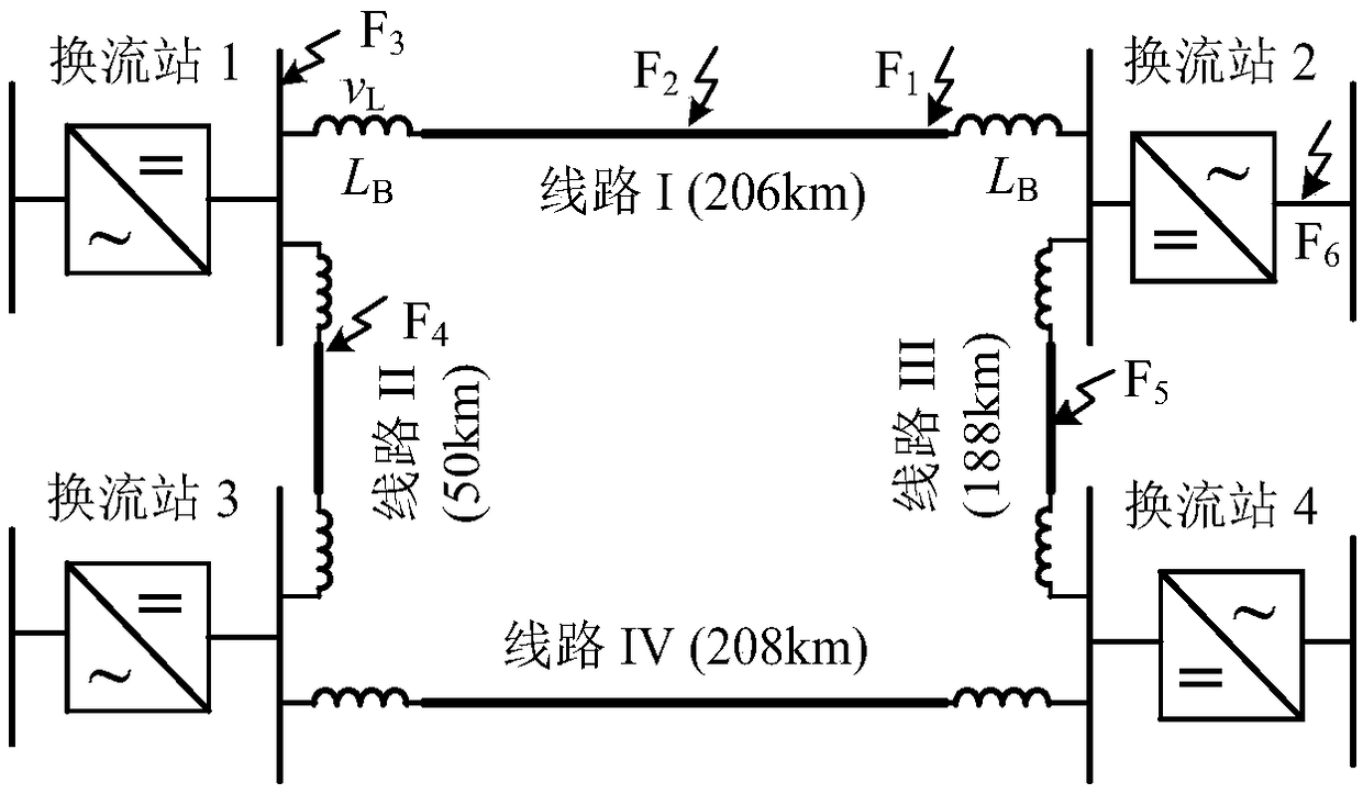
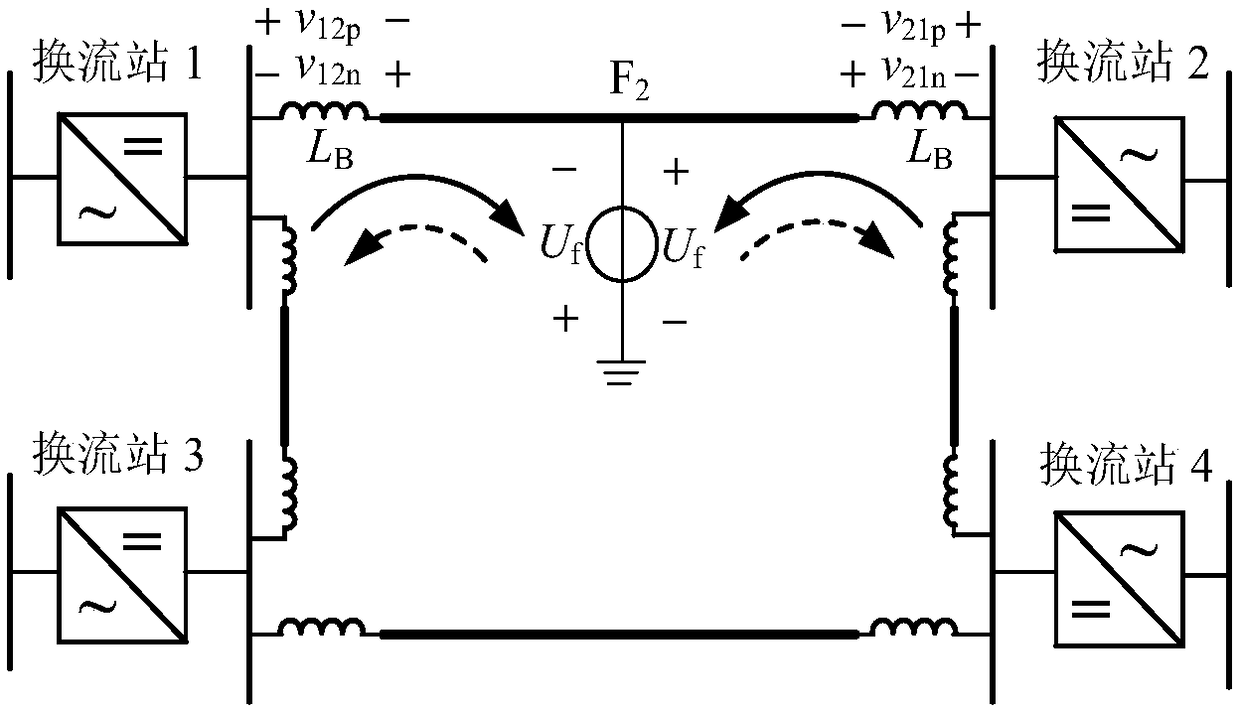
[0046] (1) Let the two ends of the line be the M terminal and the N terminal respectively, and collect the voltage value v of the current-limiting inductor at both ends of the DC line in real time Li(i represents the positive pole p or negative pole n at one end of the DC line);

[0047] (2) Using the voltage gradient algorithm to v Li To process, and then detect whether there is a fault;

[0048] The fault detection criterion and calculation expression are shown in the following formula,

[0049] |▽v L (k)|>Δ 1 (1)

[0050]

[0051] In the formula, v L (k),▽v L (k) are the voltage value and voltage gradient value of the kth sampling point on the current-limiting inductor; Δ 1 is the starting threshold; k and j are samp

Embodiment 2

[0130] In some embodiments, a multi-terminal flexible direct current grid pilot protection system based on the voltage polarity of the current-limiting inductor is disclosed, including a server, the server includes a memory, a processor, and a memory stored on the memory and can run on the processor A computer program, the processor implements the multi-terminal flexible DC grid longitudinal protection method based on the voltage polarity of the current-limiting inductor described in Embodiment 1 when executing the program.

Embodiment 3

[0132]In some embodiments, a computer-readable storage medium is disclosed, on which a computer program is stored. When the program is executed by a processor, the multi-terminal flexible DC grid based on the voltage polarity of the current-limiting inductor described in Embodiment 1 is implemented. Pilot protection method.


PUM


Abstract

The invention discloses a multi-terminal flexible DC network longitudinal protection method and system based on current limiting inductor voltage polarity, which comprises the following steps: collecting voltage values of current limiting inductor at both ends of a DC line in real time; detecting voltage values of current limiting inductor at both ends of the DC line in real time; Voltage gradientalgorithm is used to deal with the voltage, and then to detect whether there is a fault; After the protection is started, the current-limiting inductor voltage in the sampling data window is integrated, and the current-limiting inductor voltage polarity is judged by comparing the integrated value S with the set threshold value. The current limiting inductor voltage polarity R at both ends of theline is compared, and if both polarities are positive, the fault is judged to be in-area fault, otherwise, the fault is judged to be out-of-area fault. The protection principle and algorithm of the invention are simple, and do not need mathematical tools such as fast Fourier transform, wavelet transform and the like for frequency division or traveling wave capture, and also do not need data synchronization at both ends of the line, and are easy to realize. The data window of the protection criterion is short, and no additional fault pole identification step is needed, so the protection criterion is fast.

Description


Claims


Application Information

Patent Timeline
Owner SHANDONG UNIV
Why Eureka
Try Eureka