Waterfall type cap sorter

A cap-arranging machine and waterfall technology, which is applied to conveyor objects, transportation and packaging, etc., can solve the problems of stains, poor appearance of bottle caps, and high rejection rate, and achieve the effect of convenient maintenance and improved finishing effect.

Inactive Publication Date: 2019-01-25
广州市比美高智能系统科技有限公司
View PDF7 Cites 1 Cited by
  • Summary
  • Abstract
  • Description
  • Claims
  • Application Information

AI Technical Summary

Problems solved by technology

[0005] The existing cap unscrambling machine has the following defects: 1. The direction of the bottle cap is not easy to be controlled, resulting in a bad finishing ef

Method used


Image

  • Waterfall type cap sorter
  • Waterfall type cap sorter
  • Waterfall type cap sorter

Examples


Embodiment Construction

[0031] The present invention will be further described below in conjunction with the accompanying drawings, but the protection scope of the present invention is not limited to the following description.

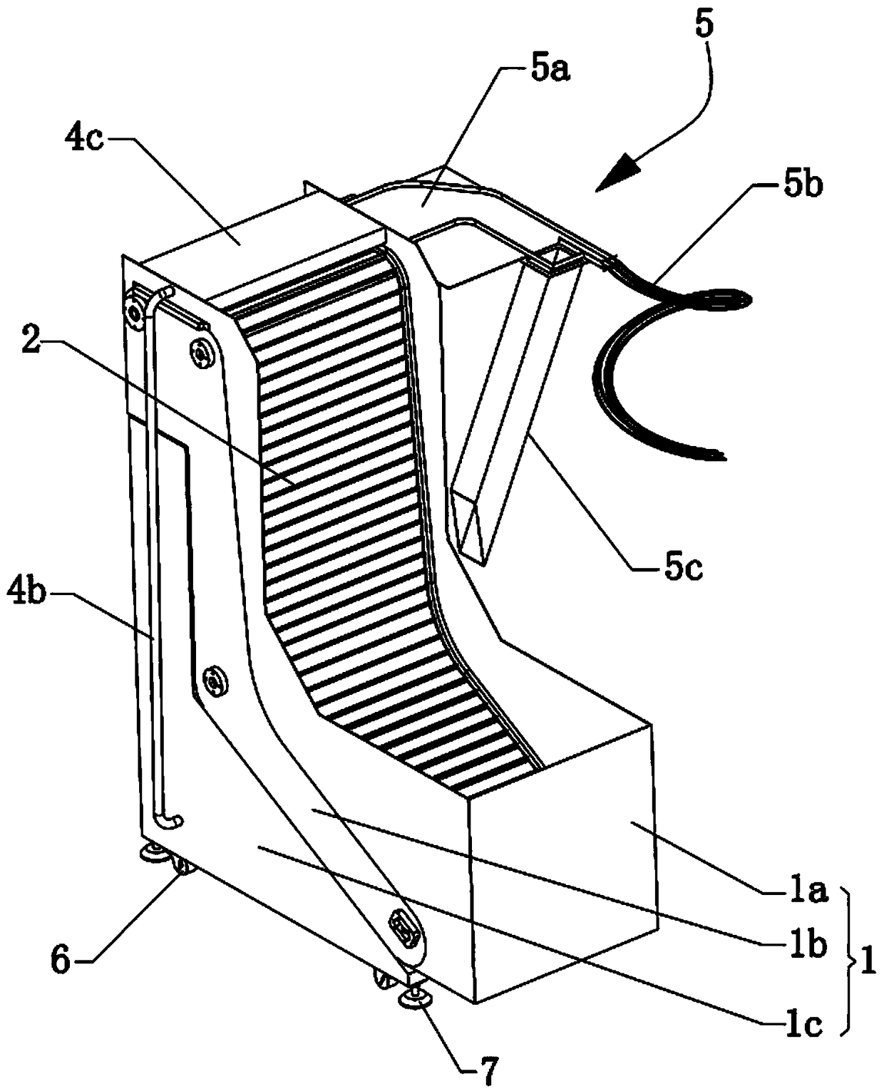
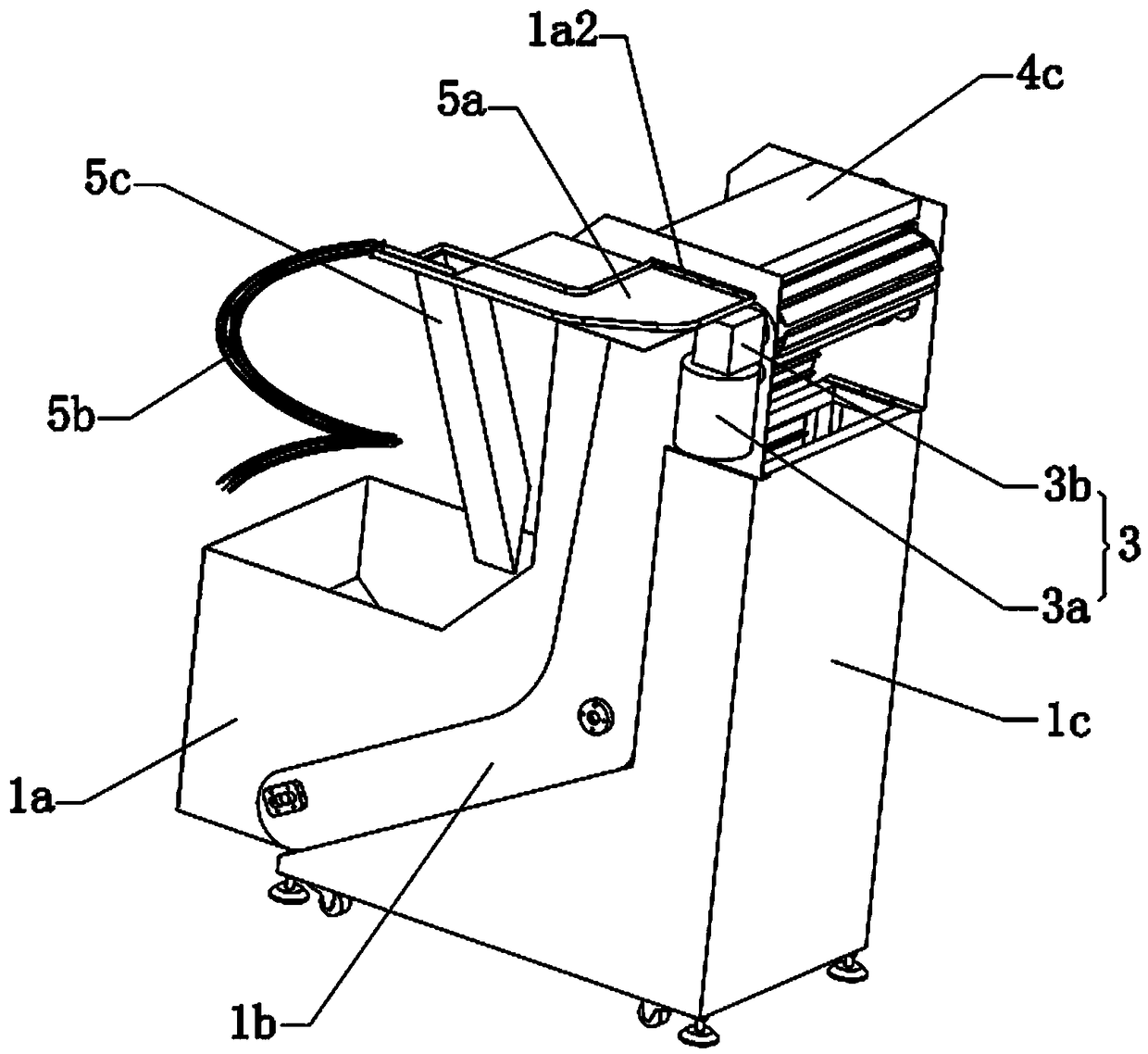
[0032] Such as Figure 1 to Figure 4 As shown, the waterfall cap sorting machine includes a casing assembly 1, a bottle cap conveying assembly 2, a driving assembly 3, a pneumatic conveying assembly 4 and a return assembly 5, and the bottle cap conveying assembly 2 is arranged on the inside of the casing assembly 1, The driving assembly 3 is transmission-connected with the bottle cap conveying assembly 2, the return assembly 5 is arranged on the top side of the casing assembly 1, the bottle cap is mounted on the lower part of the casing assembly 1, and the driving assembly 3 drives the bottle cap conveying assembly 2 The bottle caps are transported to the top of the bottle cap conveying assembly 2, and the bottle caps are sent to the return assembly 5 by starting the conveying a


PUM


Abstract

The invention relates to the technical field of automatic machinery, in particular to a waterfall type cap sorter. The waterfall type cap sorter comprises a housing assembly, a bottle cap conveying assembly, a driving assembly, a pneumatic conveying assembly and a backflow assembly, wherein the bottle cap conveying assembly is arranged on the inner side of the housing assembly, the driving assembly is in driving connection with the bottle cap conveying assembly, the backflow assembly is arranged on one side of the top of the housing assembly, bottle caps are arranged at the lower portion of the housing assembly, the driving assembly drives the bottle cap conveying assembly to convey the bottle caps to the top of the bottle cap conveying assembly, the bottle caps are blown to the backflow assembly by starting the conveying assembly, the bottle cap conveying assembly can make openings of the bottle caps to always face the outer side in the conveying process. The waterfall type cap sorterhas the advantages that the bottle cap conveying assembly makes the bottle caps with the openings outward to be left in the conveying process, the bottom caps with the openings inward are removed, itis achieved that the bottle caps are consistent in opening direction, and the bottle cap sorting effect is improved; in the bottle cap conveying process, the bottle caps are not in contact with a groove wall, and the problem is solved that a conventional turntable type cap sorter causes stains due to multiple times of back-and-forth friction.

Description


Claims


Application Information

Patent Timeline
Owner 广州市比美高智能系统科技有限公司
Why Eureka
Try Eureka