Horizontal moving cylindrical shaft head turning equipment

A technology of horizontal movement and head turning, which is applied in turning equipment, turning equipment, metal processing equipment, etc., can solve the problems of complicated movement and positioning operations, difficult disassembly and replacement of turning heads, and difficulty in ensuring accurate position, so as to improve construction efficiency. and construction accuracy, improve construction efficiency, quality and efficiency, and facilitate the effect of fast and accurate movement

Pending Publication Date: 2019-03-19
罗甸县金泰模具机械制造有限公司
View PDF0 Cites 0 Cited by
  • Summary
  • Abstract
  • Description
  • Claims
  • Application Information

AI Technical Summary

Problems solved by technology

Due to the large size and complex structure of the existing cylindrical grinder, the turning head is difficult to disassemble and assemble. During the processing and production process, the turning head is often shut down for maintenance due to damage to the turning head; Move to the site to be constructed, but it is difficult to ensure the accuracy of the position when the cylindrical grinder moves at the bottom of the large workpiece, and it is difficult to fix after moving to the constru

Method used


Image

  • Horizontal moving cylindrical shaft head turning equipment
  • Horizontal moving cylindrical shaft head turning equipment
  • Horizontal moving cylindrical shaft head turning equipment

Examples


Embodiment Construction

[0032] The present invention will be further described below in conjunction with the accompanying drawings and embodiments, but not as a basis for limiting the present invention.

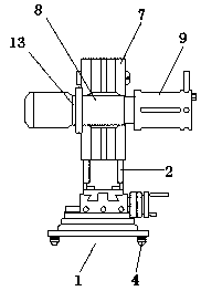
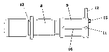
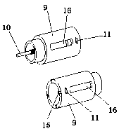
[0033] Example. Horizontal movement of external spindle turning equipment such as Figure 1 to Figure 13 As shown, it includes a mobile base device 1, a guide rail is provided below the mobile base device 1, and a column 2 is provided above the mobile base device 1. The mobile base device 1 includes a base plate 3, and an electromagnet is provided at the center of the bottom of the base plate 3. , the four corners below the base plate 3 are provided with a group of ball screws 4, and the setting positions of the ball screws 4 are aligned with the guide rails; the top of the base plate 3 is provided with a positioning installation turntable 5, and the top of the positioning installation turntable 5 is provided with a rotary knife feed seat 6; the positioning installation Bolt grooves are arranged in th


PUM


Abstract

The invention discloses horizontal moving cylindrical shaft head turning equipment. The horizontal moving cylindrical shaft head turning equipment comprises a moving base device, guide rails are arranged under the moving base device, and stand columns are arranged over the moving base device; the moving base device comprises a base disc, the four corners of the lower portion of the base disc are provided with a group of ball screws, and the positions of the ball screws are aligned with those of the guide rails; and a sliding block is arranged on one side of each stand column, and a shaft headturning device is arranged on the sliding blocks. According to the horizontal moving cylindrical shaft head turning equipment, the size is small, carrying is convenient, use is convenient, dismountingis easy, maintenance and replacement are convenient, the cylindrical shaft head turning construction requirements are met, and the construction efficiency and quality are improved; and meanwhile, quick and accurate moving is convenient, positioning operation is easy after the equipment arrives at the construction position, and the construction efficiency and the construction precision can be effectively improved.

Description


Claims


Application Information

Patent Timeline
Owner 罗甸县金泰模具机械制造有限公司
Why Eureka
Try Eureka