Automatic spot drill motor speed control method

A technology for speed control and drilling rigs, which is applied in the direction of electric speed/acceleration control, etc., can solve the problems of spot drilling rig material drill drop-off, material drilling position, equipment cost increase, spot drilling rig vibration, etc., to avoid material drill falling off and low cost , to meet the needs of the controller

Active Publication Date: 2019-03-22
ZHEJIANG UNIV OF TECH
View PDF12 Cites 4 Cited by
  • Summary
  • Abstract
  • Description
  • Claims
  • Application Information

AI Technical Summary

Benefits of technology

This patented technology helps prevent damage from dropping materials down while moving tools at different speeds without losing accuracy or causing issues with other components such as sensors used for feedback control purposes. By implementing this algorithm, an accelerator equipped tool becomes more reliable over time by reducing computational load and processing delays compared to previous methods like linear programming techniques. Additionally, it uses advanced algorithms called Strobe Programming (STMP), allowing for fast changes between various modes of operation depending upon factors like power supply voltage levels. Overall, these technical improvements help ensure accurate and efficient work results when utilizing automated points drills.

Problems solved by technology

This patented technical problem addressed by this patents relates to improving the performance and reliability of an automated spot driller (SPDM) system used with these types of machines due to their heavy loads caused by moving parts that require constant accelerations or slow movements when they perform certain operations such as spot drills.

Method used


Image

  • Automatic spot drill motor speed control method
  • Automatic spot drill motor speed control method
  • Automatic spot drill motor speed control method

Examples


Embodiment Construction

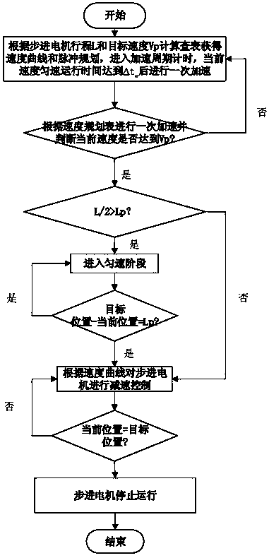
[0015] Embodiments of the present invention will be further described below in conjunction with the accompanying drawings. refer to figure 1 and figure 2 , a kind of automatic point drilling machine speed control method, described method comprises the following steps:

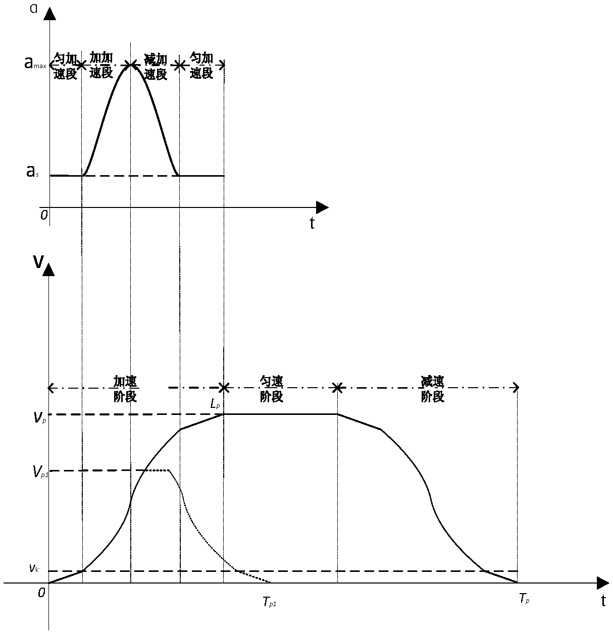
[0016] 1)a max It is the maximum acceleration that can be tolerated according to the torque-frequency characteristics of the spot drill stepper motor and the mechanical structure of the spot drill; acceleration a s Through on-site testing, it can effectively prevent the material drill from falling off and the position of the material drill from shifting; the acceleration planning table (a 1 ,a 2 ,···,a n ), the subscripts 1 to n represent the planning sequence of the acceleration, and a represents the value of the acceleration;

[0017] 2) Point drill motor every acceleration cycle Δt n Perform a speed increase, Δt n is proportional to the current speed of the spot drill stepper motor, combined with step


PUM


Abstract

An automatic spot drill motor speed control method includes following steps: 1), acquiring acceleration planning charts (a1, a2,..., an); 2), setting acceleration period of each time of acceleration as delta tn which refers to time for which current speed needs to be maintained to run for delta tn before nth acceleration, and combining speed planning charts (v1, v2, ..., vn) of a motor acquired inthe step 1) by calculation and pulse planning charts (l1, l2, ..., ln) of pulse number needed for reaching target speed, wherein delta tn is in direct proportion to the current speed of a spot drillstepping motor, and minimum acceleration period is delta t; 3),calculating according to the target position and the current position of the spot drill motor to acquire stroke L, combining vp and L, and comparing values in the speed planning charts and the pulse planning charts of the step 2) to acquire a speed control curve meeting the speed planning charts and the pulse planning charts, wherein the target speed is vp. By the method, quick acceleration of the spot drill stepping motor can be realized, and working stability and efficiency of the spot drill motor can be improved.

Description


Claims


Application Information

Patent Timeline
Owner ZHEJIANG UNIV OF TECH
Why Eureka
Try Eureka