Portable intelligent clothes dryer display bracket and assembling method thereof
A clothes drying machine and portable technology, which is applied in the field of portable intelligent clothes drying machine display bracket structure, can solve the problems of many materials and parts, troublesome assembly and disassembly, inconvenient handling, etc., and achieves easy assembly, light weight and poor aesthetics. Effect
- Summary
- Abstract
- Description
- Claims
- Application Information
AI Technical Summary
Problems solved by technology
Method used
Image

Examples
Embodiment 1
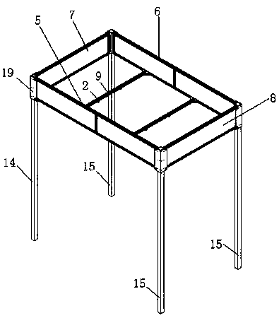
[0041] For the display bracket of the portable intelligent clothes dryer in this embodiment, refer to the attached Figure 1-13 , the display bracket of the portable intelligent clothes dryer in this embodiment includes a plurality of vertical columns, and the top of the vertical columns is equipped with detachable front frame beams 5, rear frame beams 6, left frame beams 7, right frame beams 8, front frame beams 5 and the rear frame beam 6 are installed with two mounting beams 9 that can slide left and right, and the lower surface of the two mounting beams 9 is provided with a mounting mechanism for installing a clothes hanger;
[0042] In order to make the display bracket of the portable intelligent clothes dryer have high strength, light weight, and easy to carry, the front frame beam 5, rear frame beam 6, left frame beam 7, and right frame beam 8 are all assembled from 3030 aluminum profiles;
[0043] In order to let customers know the displayed brand while displaying the clo
Embodiment 2
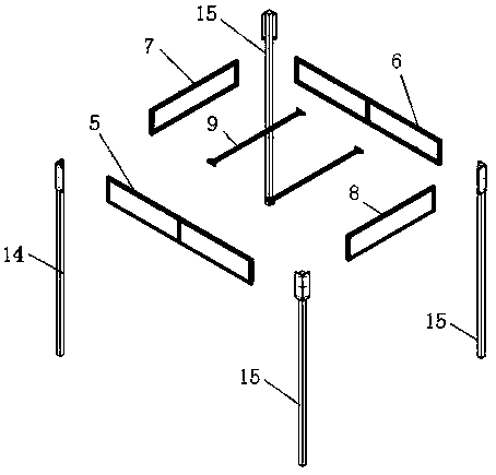
[0049] For the assembly method of a clothes dryer display rack in this embodiment, refer to the attached Figure 1-13 , including the following steps:
[0050] 1. Take an ordinary column 15, put the top of the ordinary column 15 down (that is, one end with the L-shaped angle aluminum 19 facing down), and install the front frame beam 5 and the right frame beam 8 on the L-shaped On the angle aluminum 19, with the top of the electrified column 14 facing down, install the other end of the front frame beam 5 on the L-shaped angle aluminum 19 of the electrified column 14, and then install one end of the left frame beam 7 on the L-shaped angle of the electrified column 14. On the angle aluminum 19, finally, the tops of the remaining two common columns 15 face down (that is, the end with the L-shaped angle aluminum 19 faces down), and the two ends of the rear frame beam 6 are installed between the remaining two common columns 15;
[0051] 2. Install the two mounting beams 9 between the
PUM
 Abstract
Description
Claims
Application Information
 - R&D Engineer
- R&D Manager
- IP Professional
- Industry Leading Data Capabilities
- Powerful AI technology
- Patent DNA Extraction
Browse by: Latest US Patents, China's latest patents, Technical Efficacy Thesaurus, Application Domain, Technology Topic.
© 2024 PatSnap. All rights reserved.Legal|Privacy policy|Modern Slavery Act Transparency Statement|Sitemap