Clamping caster

A snap-fit, caster technology, applied in the direction of casters, wheels, transportation and packaging, etc., can solve the problems of low concentricity of two spokes, low production efficiency, short practical life, etc., to save manpower, improve efficiency, and reliable quality Effect

Pending Publication Date: 2019-04-12
中山市威玛金属制品有限公司
View PDF0 Cites 0 Cited by
  • Summary
  • Abstract
  • Description
  • Claims
  • Application Information

AI Technical Summary

Benefits of technology

The inventor has developed a new design for a type of sling that combines both metal rods together by means of a special mechanism called a lock fit system. These systems include rings or slots along each rod's length, which match up with corresponding holes formed during manufacturing processes. When assembled this way, it forms a secure connection without any extra steps like drilling screw bolts at regular intervals. Additionally, these designs improve the performance and lifespan of the sled compared to previous methods such as welding them onto steel plates.

Problems solved by technology

Technological Problem: Current methods for joining multiple parts together like wires or brackets require manual labor that can result in lower productivity due to slow assembly time and lacking consistency between components.

Method used


Image

  • Clamping caster
  • Clamping caster
  • Clamping caster

Examples


Embodiment Construction

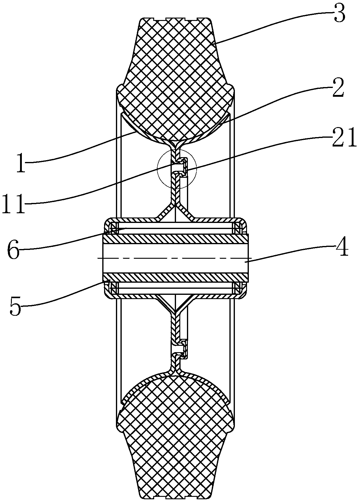
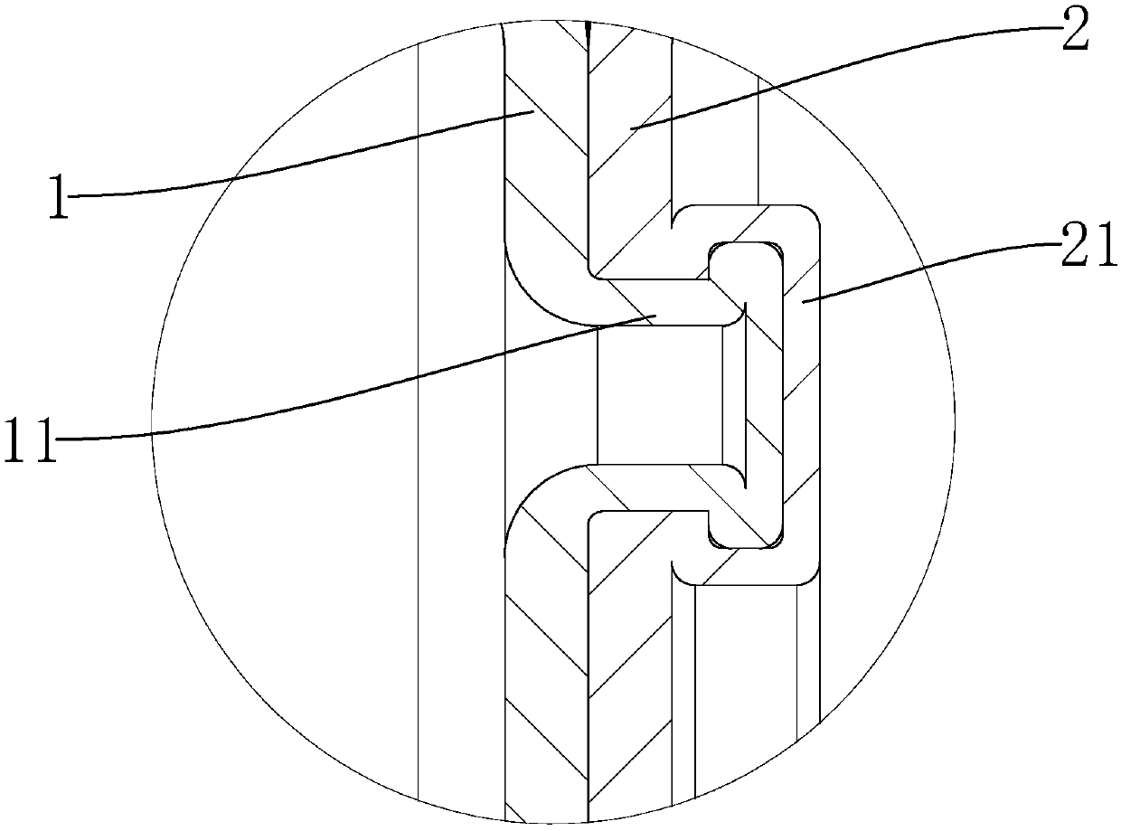
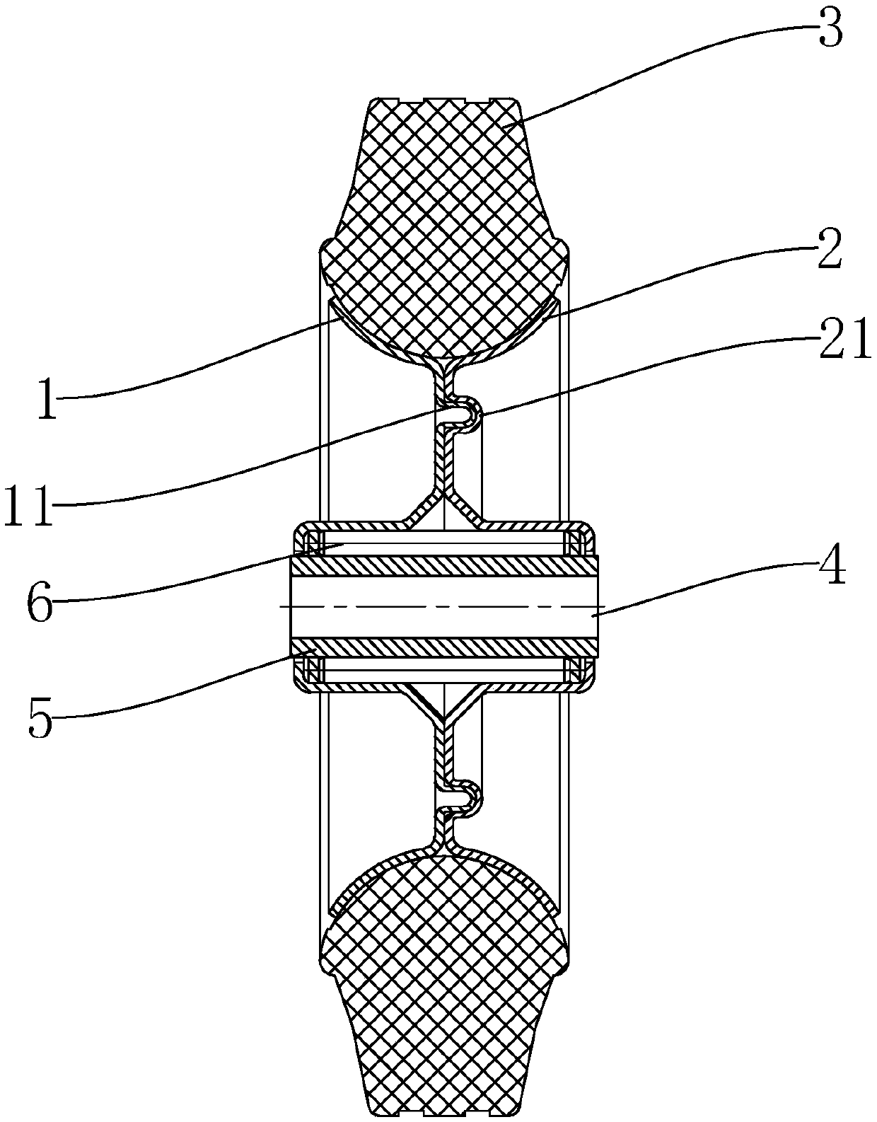
[0019] refer to Figure 1 to Figure 5 , Figure 1 to Figure 5 It is a specific structural schematic diagram of an embodiment of the present invention. As shown in the figure, a clip-on caster includes a first spoke 1, a second spoke 2 and an outer wheel 3, and the first spoke 1 and the second spoke 2 The shape is bowl-shaped, the first spoke 1 and the second spoke 2 are combined with their backs facing outward, and the first spoke 1 and the second spoke 2 are combined to form a hub through a buckle structure. In the present invention , the buckle structure includes an annular boss 11 arranged on the first spoke 1 and an annular groove 21 matched with the annular boss 11 arranged on the second spoke 2, of course, in other embodiments , the buckle structure may include an annular groove 21 arranged on the first spoke 1 and an annular boss 11 arranged on the second spoke 2 and matched with the annular groove 21, during the production process, the After the annular boss 11 and the


PUM


Abstract

The invention discloses a clamping caster which comprises a first spoke, a second spoke and an outer caster, wherein the first spoke and the second spoke are combined to form a hub through a bucklingstructure; the outer caster is arranged on the external circumference of the hub. The buckling structure comprises a circular boss or a circular groove arranged on the first spoke and a circular groove matched with the circular boss arranged on the second spoke or a circular boss matched with the circular groove formed in the second spoke. In a production process, the circular boss and the circular groove of the spokes are combined; after combination is accomplished, a binding part is subjected to pressure connection, so that the steady buckling structure is formed between the two spokes; theprocess can replace the traditional rivet mounting process; the manpower is saved; the production efficiency is improved. In addition, the concentricity of a product is improved; swinging and bouncingof the caster during rolling can be reduced; the quality is more reliable; a service life is prolonged.

Description


Claims


Application Information

Patent Timeline
Owner 中山市威玛金属制品有限公司
Why Eureka
Try Eureka