Method, device and system for measuring mechanical beam rigidity of capacitive MEMS accelerometer

A technology of accelerometer and measurement method, which is applied in the direction of speed/acceleration/shock measurement, measurement device, speed/acceleration/shock measurement equipment testing/calibration, etc. It can solve the problems of inability to accurately measure the stiffness of mechanical beams, etc., and achieve improvement The effect of measurement accuracy

Active Publication Date: 2019-04-12
CHINA ELECTRONICS PROD RELIABILITY & ENVIRONMENTAL TESTING RES INST
View PDF5 Cites 3 Cited by
  • Summary
  • Abstract
  • Description
  • Claims
  • Application Information

AI Technical Summary

Benefits of technology

This patented describes an improvement on how to measure the stifferiness (mechanism) of a type called a Capacitor Micromachined Accelerator (CMG). It involves adding two different voltages at opposite ends of the CMG's sensitive element: one with higher static electricity than another while maintaining constant pressure levels between them. These voltages are applied alternately during operation to create varying degrees of strain that affect its behavior. Based upon these measurements, it provides valuable insights into the mechanisms involved in driving various applications such as gaming machines or robotic arms.

Problems solved by technology

This patented technical problem addressed in this patents relates to improving the accuracy of detecting changes in physical properties caused by external forces applied through a specific part or device called a sensor. Traditional techniques like strain gauge are limited because they require large amounts of space that can affect their performance. Therefore there needs more accurate measurements without requiring too much room.

Method used


Image

  • Method, device and system for measuring mechanical beam rigidity of capacitive MEMS accelerometer
  • Method, device and system for measuring mechanical beam rigidity of capacitive MEMS accelerometer
  • Method, device and system for measuring mechanical beam rigidity of capacitive MEMS accelerometer

Examples


Embodiment Construction

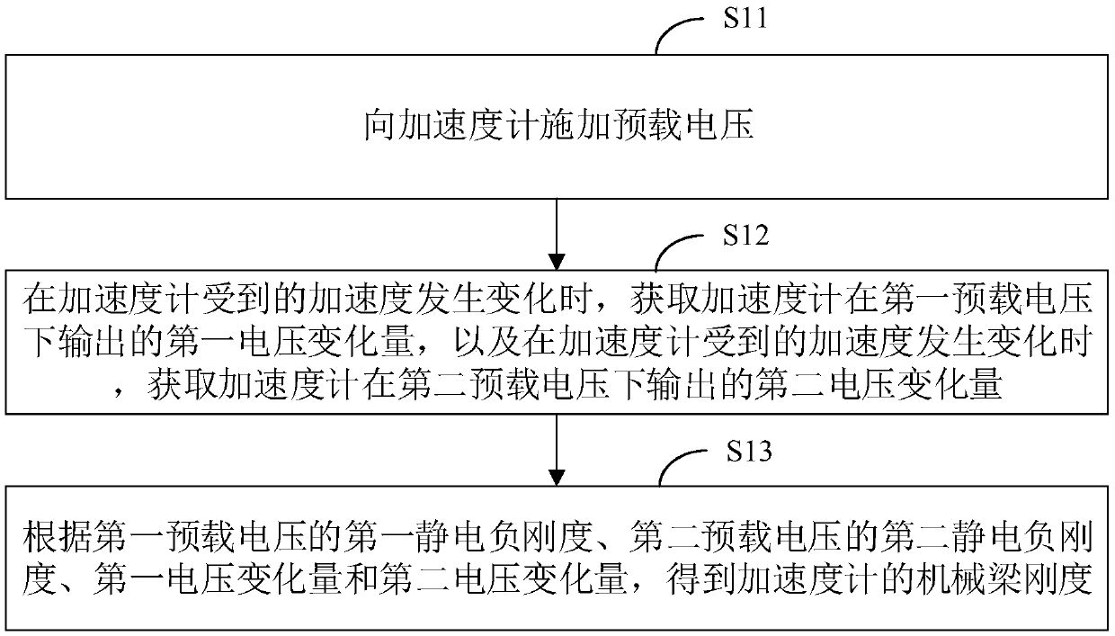
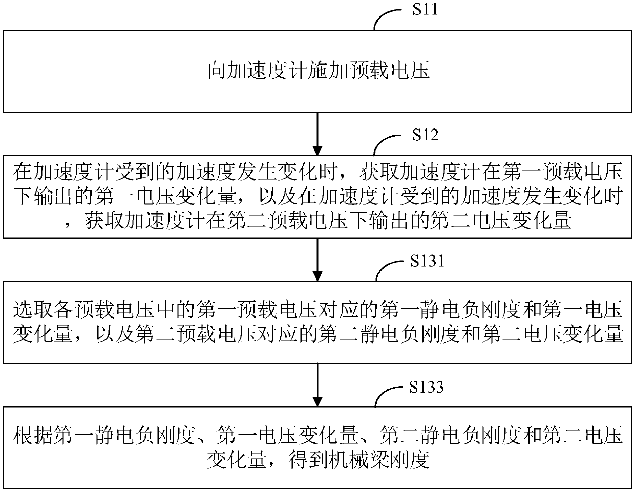
[0044] In order to make the purpose, technical solution and advantages of the present application clearer, the present application will be further described in detail below in conjunction with the accompanying drawings and embodiments. It should be understood that the specific embodiments described here are only used to explain the present application, and are not intended to limit the present application.

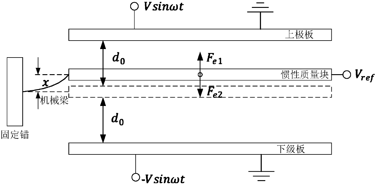
[0045] In a specific application scenario of the method, device and system for measuring the mechanical beam stiffness of a capacitive MEMS accelerometer in this application:

[0046] The traditional technology proposes a method based on Hooke's law, by applying force to the inertial mass of the sensitive structure of the capacitive MEMS accelerometer, measuring the displacement of the inertial mass under the force, and then obtaining the capacitive MEMS acceleration according to Hooke's law The mechanical beam stiffness of the gauge. However, this method has at least the foll


PUM


Abstract

The invention relates to a method, a device and a system for measuring a mechanical beam rigidity of a capacitive MEMS (Micro-Electro-Mechanical System) accelerometer. The method comprises: applying apreload voltage to the accelerometer, wherein the preload voltage comprises a first preload voltage and a second preload voltage; acquiring a first voltage change amount output by the accelerometer at the first preload voltage when the acceleration experienced by the accelerometer changes, and acquiring a second voltage change amount output by the accelerometer at the second preload voltage whenthe acceleration experienced by the accelerometer changes; and obtaining the mechanical beam rigidity of the accelerometer according to a first electrostatic negative rigidity of the first preload voltage, a second electrostatic negative rigidity of the second preload voltage, the first voltage change amount and the second voltage change amount. According to the method, the device and the system for measuring the mechanical beam rigidity of the capacitive MEMS accelerometer, the influence of the parameters, of the traditional measuring technology, such as displacement capacitance conversion coefficient, inertial mass block quality, etc., on the measurement precision when measuring the mechanical beam rigidity can be avoided, so that the measurement precision of the mechanical beam rigidityof the accelerometer is improved.

Description


Claims


Application Information

Patent Timeline
Owner CHINA ELECTRONICS PROD RELIABILITY & ENVIRONMENTAL TESTING RES INST
Why Eureka
Try Eureka