Method for electronically controlling pneumatic braking system in vehicle, and electronically controllable pneumatic braking system

A technology for pneumatic braking and commercial vehicles, which is applied to brake transmissions, brakes, vehicle components, etc., and can solve problems such as small average control pressure, reduced braking effect, and reduced service brake control pressure.

Active Publication Date: 2019-04-16
WABCO EURO BVBA SPRL
View PDF16 Cites 3 Cited by
  • Summary
  • Abstract
  • Description
  • Claims
  • Application Information

AI Technical Summary

Problems solved by technology

As a result, the service brake control pressure is reduced compared to continuous actuation, since a lower mean control pressure is achieved, which results in a reduced braking effect

Method used


Image

  • Method for electronically controlling pneumatic braking system in vehicle, and electronically controllable pneumatic braking system
  • Method for electronically controlling pneumatic braking system in vehicle, and electronically controllable pneumatic braking system
  • Method for electronically controlling pneumatic braking system in vehicle, and electronically controllable pneumatic braking system

Examples


Example Embodiment

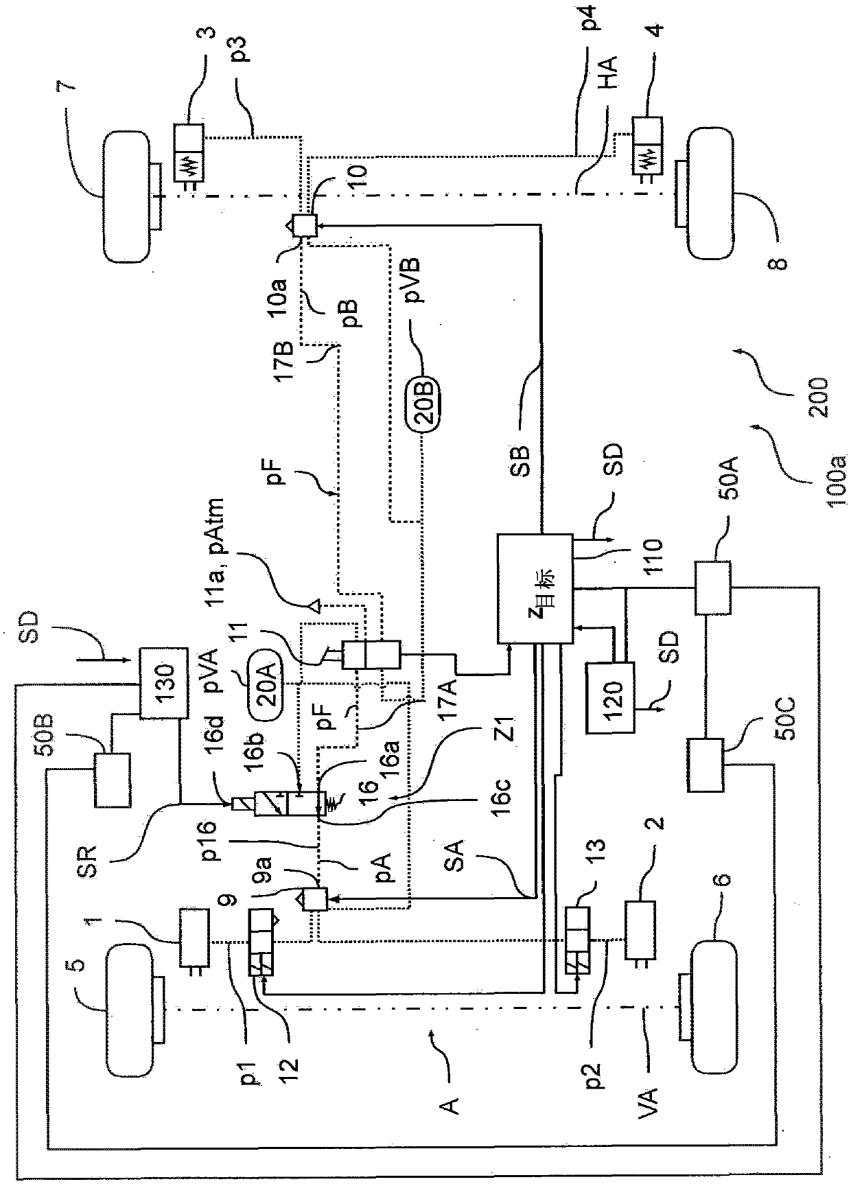
[0043] according to figure 1 A block diagram shows a section of an electro-pneumatic braking system 100a of a vehicle 200, especially a commercial vehicle, wherein the electro-pneumatic braking system is designed as an EBS braking system 100a, that is, it is implemented electrically in the normal driving mode Braking procedures. For this purpose, the EBS brake system 100a has a plurality of wheel brakes 1, 2, 3, 4, which are used to brake the vehicle 200. Two brake circuits A and B are provided for braking, and pressure medium reservoirs 20A and 20B are respectively assigned to them, so as to supply pressure medium to the respective brake circuits A and B and thus can realize the respective control of the vehicle 200 Construction of the service brake brake pressures p1, p2, p3, and p4 of the wheel brakes 1, 2, 3, and 4. There are corresponding reserve pressures pVA, pVB in each pressure medium reservoir 20A, 20B, wherein, in the first and second pressure medium reservoirs 20A, 20


PUM


Abstract

The invention relates to a method for electronically controlling a pneumatic braking system in a vehicle (200) and an electronically controllable pneumatic braking system for implementing the method.The method comprises at least the following steps: determining whether there is a failure or a malfunction in the electronic actuation of wheel brakes of the pneumatic braking system; if a failure ora malfunction in the electronic control has been determined, electronically actuating a pilot valve via a redundance signal for the redundant electropneumatic actuation of the wheel brakes; wherein the redundance signal is provided in such a way that the pilot valve alternately moves into a second switch position for a pulse time and into a first switch position for a pause time; in the first switch position, the pilot valve sets a low pressure level and in the second switch position a high pressure level as the pilot pressure; the wheel brakes are actuated with a service-brake brake pressurethat is a function of the pilot pressure; the pulse time and the pause time are set in such a way that a pilot pressure is obtained, which causes a service-brake brake pressure in the wheel brakes which, at least for a critical time, repeatedly falls below a limit pressure to produce cadence braking; and the limit pressure and the associated critical time are selected in such a way as to ensure that a wheel that is prone to blocking starts to rotate again by simply specifying the pilot pressure.

Description


Claims


Application Information

Patent Timeline
Owner WABCO EURO BVBA SPRL
Why Eureka
Try Eureka