Sound pickup device and electronic equipment

A technology for sound pickup and electronic equipment. It is used in electrical components, microphone ports/microphone accessories, sensors, etc. It can solve problems such as poor dust resistance, blocking sound holes, and affecting the appearance of electronic equipment.

Active Publication Date: 2019-04-26
SHANGHAI CHUANGGONG COMM TECH
View PDF8 Cites 1 Cited by
  • Summary
  • Abstract
  • Description
  • Claims
  • Application Information

AI Technical Summary

Problems solved by technology

However, the inventors have found that there are at least the following problems in the prior art: using a microphone to pick up sound requires multiple sound outlets on the housing of the electronic device, which affects the appearance of

Method used


Image

  • Sound pickup device and electronic equipment
  • Sound pickup device and electronic equipment
  • Sound pickup device and electronic equipment

Examples


Embodiment Construction

[0022] In order to make the purpose, technical solutions and advantages of the embodiments of the present invention more clear, various implementation modes of the present invention will be described in detail below in conjunction with the accompanying drawings. However, those of ordinary skill in the art can understand that, in each implementation manner of the present invention, many technical details are provided for readers to better understand the present application. However, even without these technical details and various changes and modifications based on the following embodiments, the technical solution claimed in this application can also be realized; and the division of the following embodiments is for convenience of description, and should not be used for the specific implementation of the present invention The mode constitutes any limitation, and the various implementation modes can be combined with each other and utilized on the premise of no contradiction.

[0023


PUM


Abstract

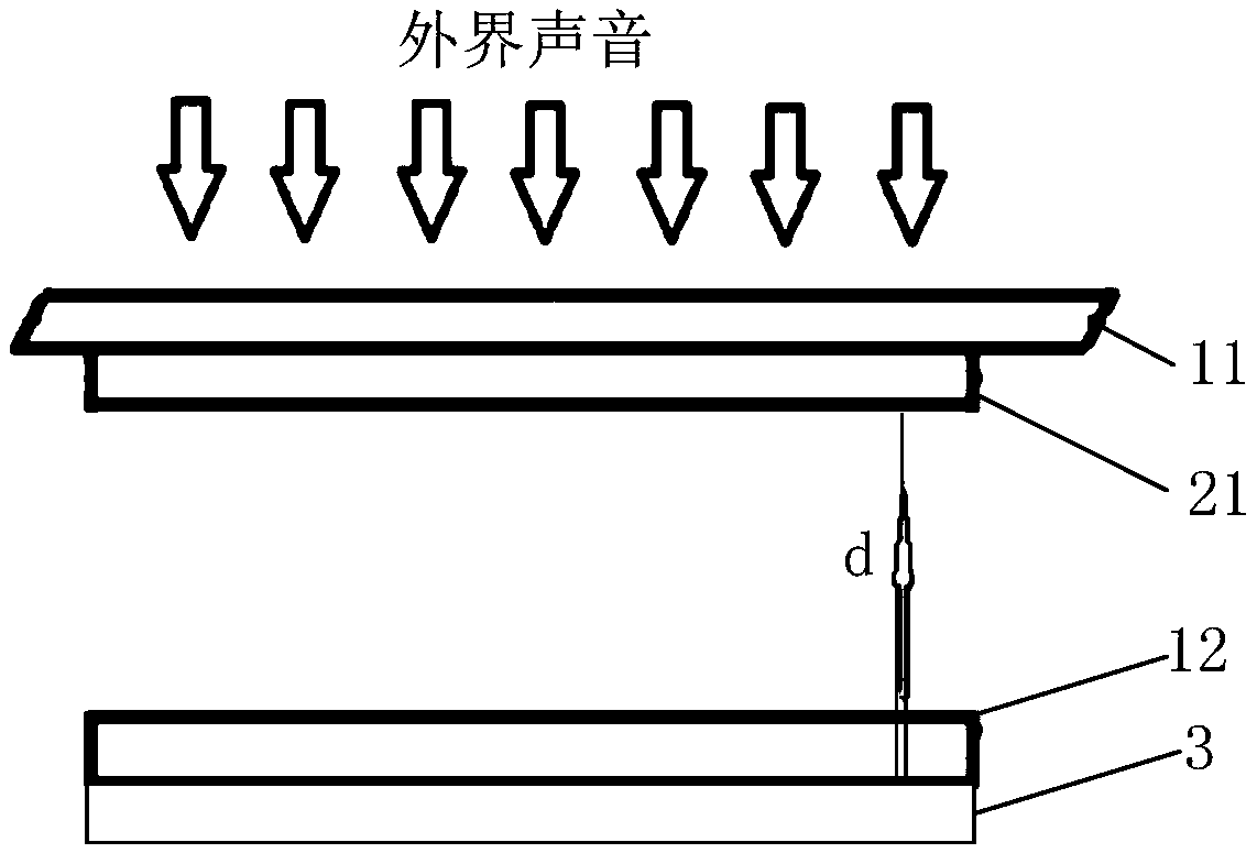
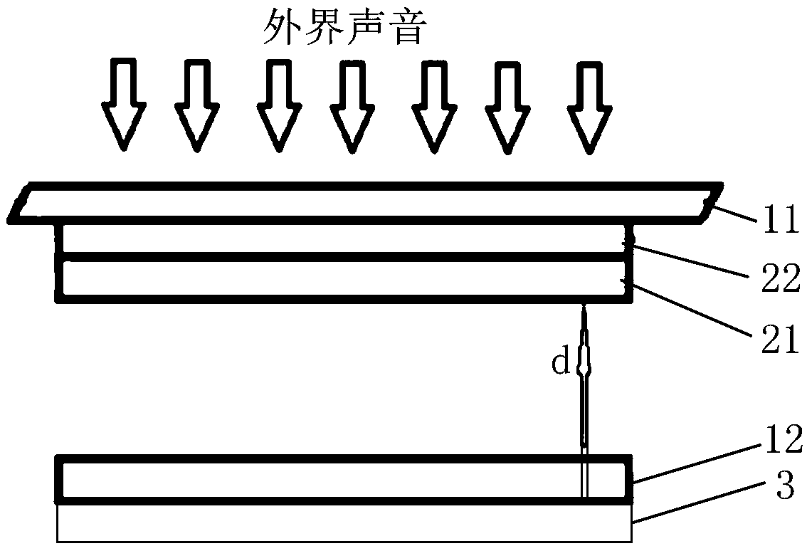
Embodiments of the invention relate to the technical field of electronic products, and disclose a sound pickup device and electronic equipment. In the embodiments of the invention, the sound pickup device comprises: a display module, an adhesive coating and a back plate, wherein the display module comprises a glass cover plate, a display screen and a bracket; the adhesive coating comprises at least a charge-retaining coating stored with a negative charge; the glass cover plate is disposed at the top of the bracket and covers the opening of the accommodating space of the bracket; the adhesive coating is applied to a preset area of the glass cover plate and located in the accommodating space; the back plate is disposed on the display and fixed at the bottom of the bracket, and a predetermined spacing is provided between the charge-retaining layer and the charge-retaining coating corresponding to the back plate; the adhesive coating and the back plate are respectively connected to the processing module of the electronic equipment. The embodiments of the invention satisfy the requirement of remote sound pickup, so that the housing of the electronic equipment does not need for sound conduction, which improves the appearance of the electronic equipment and enhances the dust resistance of the electronic equipment.

Description


Claims


Application Information

Patent Timeline
Owner SHANGHAI CHUANGGONG COMM TECH
Why Eureka
Try Eureka