Gas steaming oven

A steam box and gas technology, which is applied to steam cooking utensils, heating devices, etc., can solve problems such as safety accidents and users mistakenly turning on the gas switch, so as to reduce heat loss, improve preheating utilization, and improve compactness. Effect

Inactive Publication Date: 2019-05-14
上海温雅实业有限公司
View PDF16 Cites 1 Cited by
  • Summary
  • Abstract
  • Description
  • Claims
  • Application Information

AI Technical Summary

Problems solved by technology

However, in the actual use process, the user easily turns on the gas switch or the ignition s

Method used


Image

  • Gas steaming oven
  • Gas steaming oven
  • Gas steaming oven

Examples


Embodiment Construction

[0036] The present invention will be described in further detail below in conjunction with the accompanying drawings.

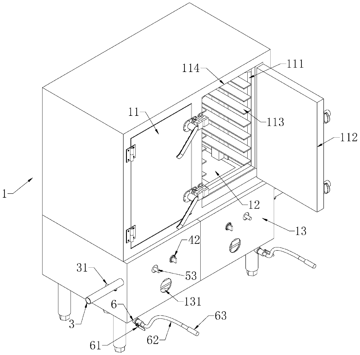
[0037] like figure 1 As shown, a gas steam box includes a box body 1. The box body 1 includes a steam chamber 11, a water tank room 12, and a combustion chamber 13 arranged vertically from top to bottom, and the box body 1 adopts a left-right symmetrical Design, that is, casing 1 includes left and right two groups of food steaming systems composed of steam chamber 11, water tank chamber 12 and combustion chamber 13. The steam chamber 11 includes a steam chamber 111 and a steam rack 113 fixed on the opposite inner walls of the steam chamber 111. The steam rack 113 is provided with a shelf for holding food, and the steam chamber 111 is located at the steam chamber opening on the front of the cabinet 1. A steam box door 112 is hinged at 114, and the steam box doors 112 of the two steam chambers 111 are arranged in opposite directions. The combustion chamber 13 is


PUM


Abstract

The invention discloses a gas steaming oven, and relates to the technical field of steaming oven equipment. The gas steaming oven comprises an oven body, wherein the oven body comprises a steam chamber and a water tank chamber, wherein a gas heating system is arranged outside the water tank chamber; the gas heating system comprises a gas delivery pipeline; the gas delivery pipeline is communicatedwith a gas-controlled combustion device and an ignition detecting device; the gas-controlled combustion device comprises a combustion head and a first valve for controlling the switching on and off of the combustion head; the ignition detecting device comprises an ignition head and a second valve for controlling the switching on and off of the ignition head; a flame probe is linked with the ignition head; the gas delivery pipeline is communicated with a third valve linked with the flame probe; the flame probe controls the switching on and off of the third valve; the first valve and the thirdvalve are connected in series, and the second valve and the third valve are connected in parallel. Ignition and combustion actions are completed through the matching of the ignition detecting device and the gas-controlled combustion device, and explosion risks caused by gas leakage of the pipeline, gas leakage of the combustion head or gas leakage of the ignition head can be reduced through the matching of the ignition detecting device and the gas-controlled combustion device, so that the purpose of increasing the using safety of the gas steaming oven can be achieved.

Description


Claims


Application Information

Patent Timeline
Owner 上海温雅实业有限公司
Why Eureka
Try Eureka