Planar transducer array and multi-mode phase control device
A transducer array and planar array technology, which is applied in the direction of measuring devices, instruments, and sound wave re-radiation, can solve problems such as inability to be fast at the same time, and achieve the effects of resource assessment integration, flexible configuration, and accurate investigation
- Summary
- Abstract
- Description
- Claims
- Application Information
AI Technical Summary
Problems solved by technology
Method used
Image

Examples
Example Embodiment
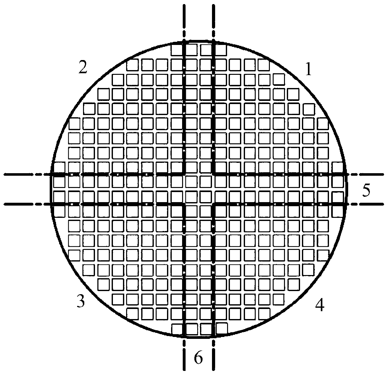
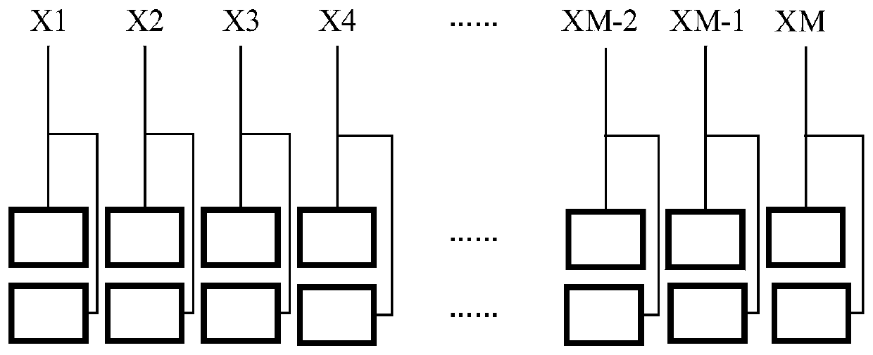
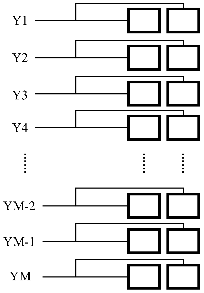
[0037] Example 1:
[0038] Combine figure 1 A schematic diagram of a planar array, defining the tap of the first quadrant as Z1, the tap of the second quadrant as Z2, the tap of the third quadrant as Z3, the tap of the fourth quadrant as Z4, and the taps of the fifth zone of the horizontal linear array as X1, X2 ,...XM-1, XM, as shown in Figure 2(a); the taps of the sixth area of the vertical linear array are Y1, Y2,..., YM-1, YM, as shown in Figure 2(b). 1 common ground tap, 1 central launch tap; 2M+6 taps in total, where M is determined by the beam width formed by a linear array. Assuming that the beam width formed by the linear array is 5°, the beam width perpendicular to the straight line is 50°, then M=20, the number of primitives perpendicular to the straight line is 2, and a total of 1 taps are connected, then the total number of taps of the planar array Then there are 46 emission taps composed of 4 primitives with a central emission primitive of 2×2, and its transmitting
PUM
 Abstract
Description
Claims
Application Information
 - R&D Engineer
- R&D Manager
- IP Professional
- Industry Leading Data Capabilities
- Powerful AI technology
- Patent DNA Extraction
Browse by: Latest US Patents, China's latest patents, Technical Efficacy Thesaurus, Application Domain, Technology Topic.
© 2024 PatSnap. All rights reserved.Legal|Privacy policy|Modern Slavery Act Transparency Statement|Sitemap