Rolling massager

A massager and rolling ball technology, which is applied to roller massage, massage aids, medicine equipment, etc., can solve the problem of single massage method and achieve the effect of small friction

Inactive Publication Date: 2019-05-31
徐涓惠
View PDF0 Cites 0 Cited by
  • Summary
  • Abstract
  • Description
  • Claims
  • Application Information

AI Technical Summary

Benefits of technology

This innovation uses a special type that has two parts - one with an inner surface made up from rubber or other elastic material for easy movement when rolled around inside it. When this new device rotates at regular intervals, its balls move backward without being influenced by external forces like gravity. By applying pressure onto these tiny particles called rolling balls, they get moved along different directions within their own protective covering layer.

Problems solved by technology

The technical problem addressed in this patented technology relates how people want their body to be more comfortable during prolonged periods without getting tired or strain from having to use an old device that was designed specifically for it purpose.

Method used


Image

  • Rolling massager
  • Rolling massager

Examples


Embodiment Construction

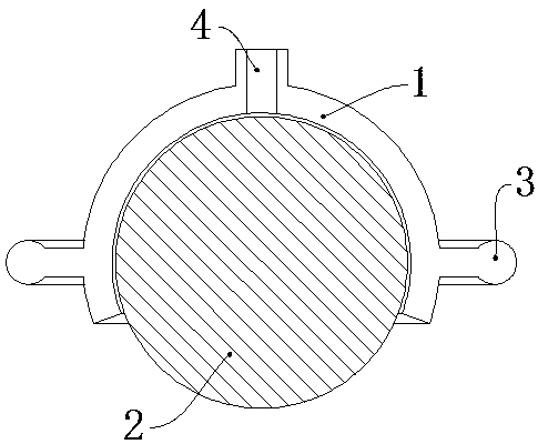
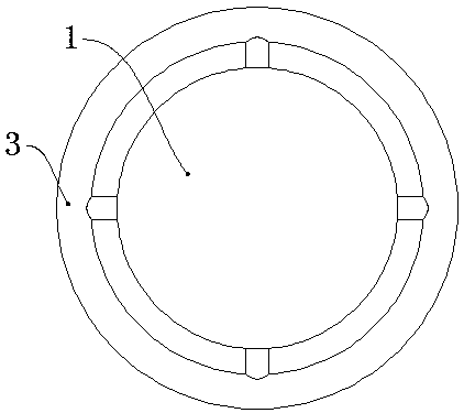
[0009] Such as figure 1 , figure 2 As shown, the rolling massager includes an outer cover 1, a rolling ball 2, and a handle 3. The outer cover 1 is a spherical shell, and the top of the outer cover 1 is provided with an oil filling port 4 connected to the inside. The lower end of the outer cover 1 is open, and the rolling ball 2 is placed Inside the outer cover 1, the bottom end of the rolling ball 2 passes through the lower end of the outer cover 1 and extends out of the outer cover 1, and the rolling ball 2 can rotate relative to the outer cover 1; the handle 3 is in the shape of a ring, and the inner side of the handle 3 is connected to the outer cover 1 through a connecting rod .


PUM


Abstract

The invention relates to a rolling massager comprising a cover, a ball and a handle. The cover is a spherical shell. The top of the cover is provided with a fuel injection port communicated to the inside, the lower end of the cover is open, and the ball is placed in the cover. The bottom end of the ball stretches out of the lower end of the cover, and the ball rotates relative to the cover. The handle is annular, and the inner side of the handle and the cover are connected by a connecting rod. The ball is adopted as the rolling portion and can roll in any direction. Massage oil can be injectedinto the cover through the fuel injection port. On one hand, the friction between the ball and the cover is small, and the normal rotation of the ball is not affected; on the other hand, the traditional massage mode is changed, and a user does not need apply the massage oil onto the body before massage.

Description


Claims


Application Information

Patent Timeline
Owner 徐涓惠
Why Eureka
Try Eureka