Device for perceiving oceanic turbulence and oceanic particles based on laser interference

A laser interference and marine technology, applied in the field of optical analog detection, can solve problems such as difficult to effectively perceive changes in turbulence intensity and particle concentration at the same time

Inactive Publication Date: 2019-06-14
HARBIN INST OF TECH
View PDF8 Cites 0 Cited by
  • Summary
  • Abstract
  • Description
  • Claims
  • Application Information

AI Technical Summary

Benefits of technology

This patented technology helps separate out both turbulences (the movement) and small objects like sea water that are moving around at different speeds by analyzing their brightness variations over time. It also captures important details about these movements such as how they move through space or reflect off land surfaces during times when there're no wind blowings on them. These technical benefits make it possible for this system to provide accurate data related to tidal fields without being affected by factors like weather conditions.

Problems solved by technology

This patented technical problem addressed in this patents relates to accurately measuring sea surface conditions without interferring with the operation or performance of equipment used during exploration activities like oil wells. Current technologies have limitations due to factors including turbulences affecting optical measurements (such as phase difference) and poor sampling efficiency associated with traditional techniques.

Method used


Image

  • Device for perceiving oceanic turbulence and oceanic particles based on laser interference
  • Device for perceiving oceanic turbulence and oceanic particles based on laser interference
  • Device for perceiving oceanic turbulence and oceanic particles based on laser interference

Examples


specific Embodiment approach 1

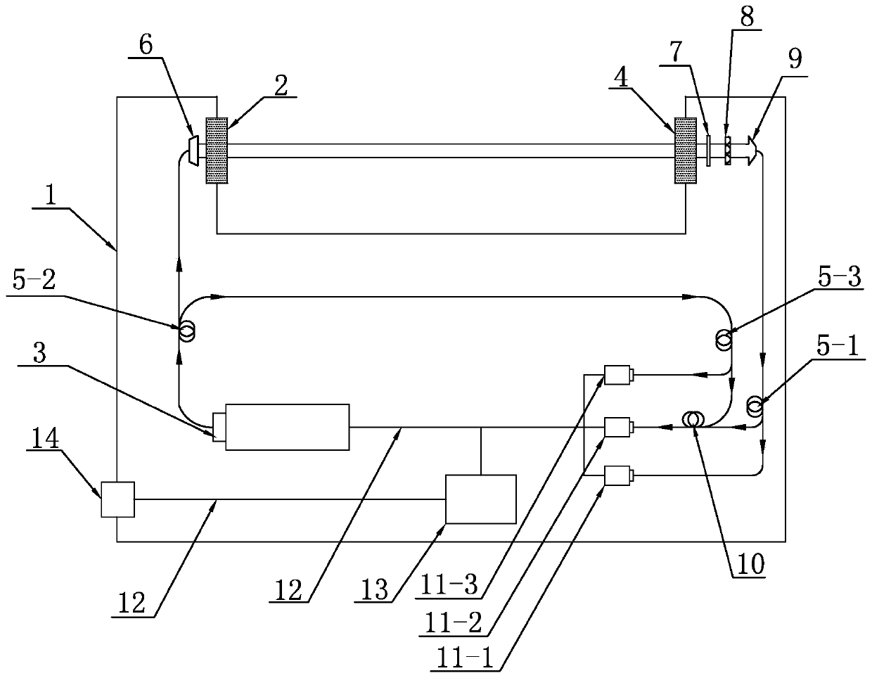
[0015] Specific implementation mode one: the following combination figure 1 This embodiment will be specifically described. This embodiment is a device for sensing ocean turbulence and ocean particles based on laser interference, which is characterized by comprising: a waterproof package shell 1, a first waterproof light-transmitting window 2, a second waterproof light-transmitting window 4, a continuous single longitudinal mode laser 3, Single-mode optical fiber, first optical fiber splitter 5-1, second optical fiber splitter 5-2, third optical fiber splitter 5-3, fiber-spatial optical coupler 6, filter plate 7, polarizer 8, Spatial light-fiber coupler 9, fiber combiner 10, first photodetector 11-1, second photodetector 11-2, third photodetector 11-3, signal supply cable 12 and control analysis system 13 ;

[0016] The laser light is emitted by the continuous single longitudinal mode laser 3, and is divided into two paths by the second optical fiber beam splitter 5-2 via the s

specific Embodiment approach 2

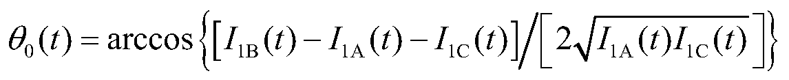
[0023] Embodiment 2: This embodiment is a further description of Embodiment 1. The difference between this embodiment and Embodiment 1 is that the control and analysis system (13) controls the first photodetector (11-1), the second The sequential electrical signals transmitted by the second photodetector (11-2) and the third photodetector (11-3) perform the following analysis process:

[0024] Step 1: put the device into the water area to be tested, at this time, the control analysis system (13) passes through the first photodetector (11-1), the second photodetector (11-2) and the third photodetector (11-1) 3) Simultaneously collect a section of sequential electrical signal I A (t), I B (t), I C (t), the sampling time is not less than 1 minute, and the sampling frequency is not less than 50Hz;

[0025] Step 2: The control and analysis system (13) performs primary filtering on the three-segment signals obtained in step 1: if the control and analysis system (13) provides photode

specific Embodiment approach 3

[0036] Embodiment 3: This embodiment is a further description of Embodiment 1. The difference between this embodiment and Embodiment 1 is that the diameter of the light beam incident on the water body in the device is 0.5cm-1cm.


PUM

PropertyMeasurementUnit
Diameteraaaaaaaaaa

Abstract

The invention discloses a device for perceiving oceanic turbulence and oceanic particles based on laser interference, relates to the technical field of optical simulation detection, and aims to solvethe problem that in the prior art, a single measurement system is unlikely to effectively separate a turbulence signal and a particle signal during simultaneous perception of the turbulence intensitychange and the particle concentration change. The device comprises a waterproof packaged shell, a first waterproof light-transmitting window, a second waterproof light-transmitting window, a continuous single longitudinal mode laser, a single mode optical fiber, a first optical fiber beam splitter, a second optical fiber beam splitter, a third optical fiber beam splitter, an optical fiber spatialoptical coupler, a filter, a polarizer, a spatial light optical fiber coupler, an optical fiber beam combiner, a first photoelectric detector, a second photoelectric detector, a third photoelectric detector, a signal power supply cable and a control analysis system. The device can effectively and simultaneously perceive the turbulence signal and the particle signal. The device can be widely applied to the field of oceanic exploration.

Description


Claims


Application Information

Patent Timeline
Owner HARBIN INST OF TECH
Why Eureka
Try Eureka