Image splicing method and system and electronic equipment
An image mosaic and image technology, applied in the field of image recognition, can solve the problems of poor image mosaic effect of pipeline welds
- Summary
- Abstract
- Description
- Claims
- Application Information
AI Technical Summary
Problems solved by technology
Method used
Image

Examples
Embodiment 1
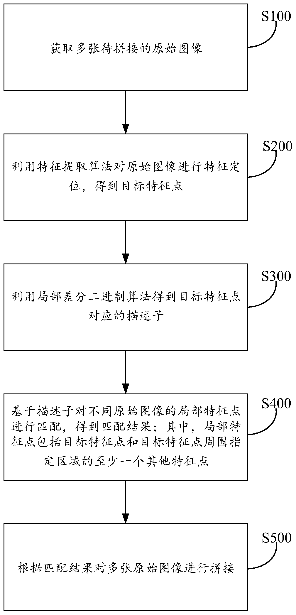
[0068] The embodiment of the present invention provides an image splicing method, which is applied to the weld detection of pipeline facilities, such as figure 1 As shown, the method includes:
[0069] Step S100, acquiring multiple original images to be spliced.
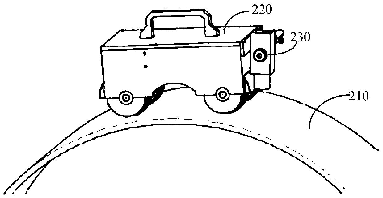
[0070] specific, figure 2 In the pipeline weld image acquisition device shown, the original image is acquired by the image acquisition device 230 installed on the trolley 220, and the image acquisition device 230 is composed of a CCD camera and a matching lens. Since the brightness difference on the surface of the pipeline is large, and the original image collected by the image acquisition device 230 will be distorted, the imaging effect of the welding area on the edge of the image will be poor, which will affect the subsequent splicing work. For the image in the middle position, the image with poor edge imaging quality is discarded.
[0071] According to the preset photographing position and photographing timing, t
Embodiment 2
[0134] An embodiment of the present invention provides an image mosaic system, the schematic diagram of which is shown in Figure 6 As shown, among them, the system includes:
[0135] An image acquisition unit 610, configured to acquire multiple original images to be spliced;
[0136] A feature extraction unit 620, configured to perform feature location on the original image using a feature extraction algorithm to obtain target feature points;
[0137] A calculation unit 630, configured to obtain a descriptor corresponding to the target feature point by using a local differential binary algorithm;
[0138] A matching unit 640, configured to match local feature points of different original images based on descriptors to obtain a matching result; wherein, the local feature points include target feature points and at least one other feature point in a specified area around the target feature point;
[0139] A splicing unit 650, configured to splice multiple original images accordi
Embodiment 3
[0142] An electronic device provided by an embodiment of the present invention, Figure 7 It is a schematic structural diagram of the electronic device. The electronic device 700 includes a memory 701 and a processor 702, wherein the memory 701 is used to store a computer program that can run on the processor 701; when the processor 702 executes the computer program, the first embodiment is implemented. The steps of the image stitching method; the electronic device further includes a bus 703 and a communication interface 704 , and the memory 701 and the communication interface 704 are connected through the bus 703 .
[0143] Wherein, the memory 701 may include a high-speed random access memory (RAM, Random Access Memory), and may also include a non-volatile memory (non-volatile memory), such as at least one disk memory. The communication connection between the system network element and at least one other network element is realized through at least one communication interface 70
PUM
 Abstract
Description
Claims
Application Information
 - R&D Engineer
- R&D Manager
- IP Professional
- Industry Leading Data Capabilities
- Powerful AI technology
- Patent DNA Extraction
Browse by: Latest US Patents, China's latest patents, Technical Efficacy Thesaurus, Application Domain, Technology Topic.
© 2024 PatSnap. All rights reserved.Legal|Privacy policy|Modern Slavery Act Transparency Statement|Sitemap