Pediatric ear spraying device
A sprayer and ear technology, applied in the field of pediatric ear sprayer, can solve problems such as slow work efficiency, eardrum puncture, and cotton swab not being applied
- Summary
- Abstract
- Description
- Claims
- Application Information
AI Technical Summary
Benefits of technology
Problems solved by technology
Method used
Image

Examples
Embodiment 1
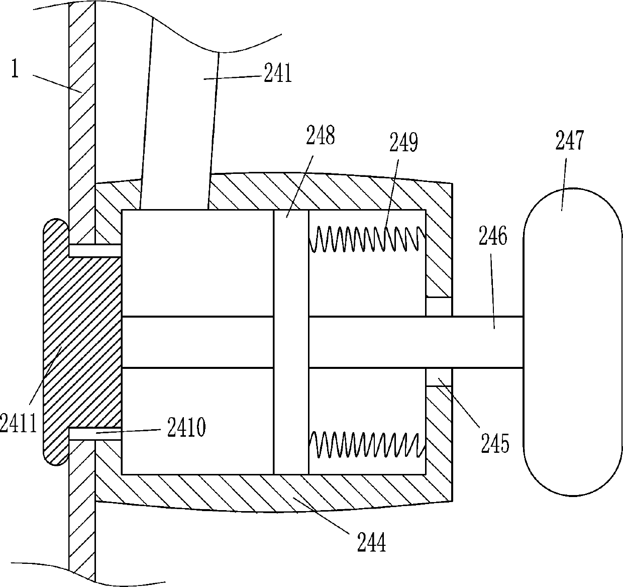
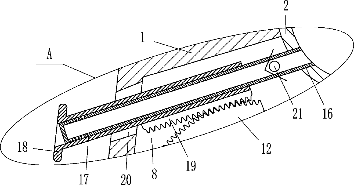
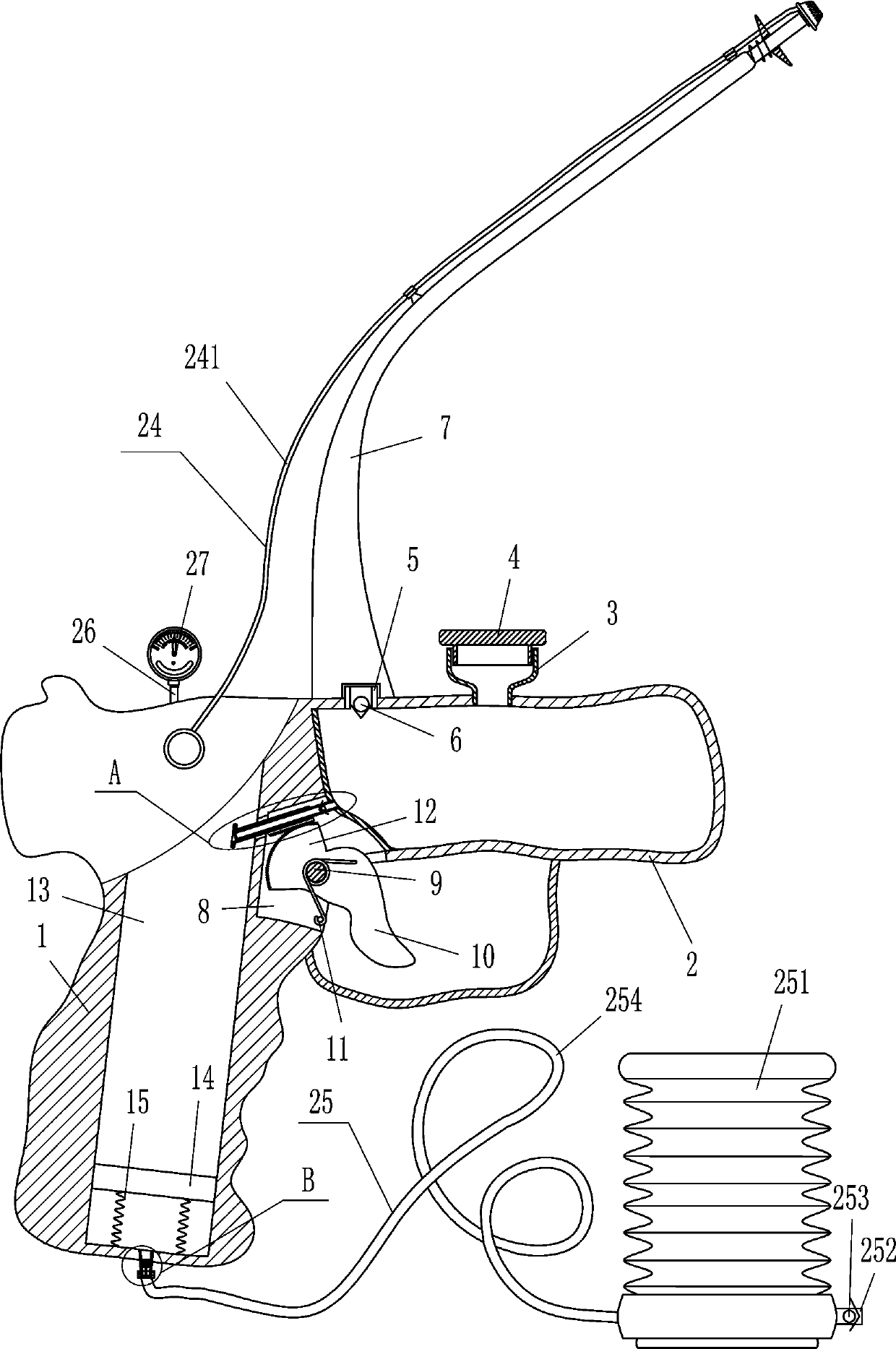
[0023]A pediatric ear sprayer such as Figure 1-5 As shown, it includes a handle 1, a housing 2, a discharge pipe 3, a plug 4, a discharge pipe 5, a first one-way valve 6, a hard pipe 7, a rotating shaft 9, a pull rod 10, a torsion spring 11, a sector gear 12, Movable plate 14, the first spring 15, sleeve 16, sleeve pipe 18, tooth bar 19, the second one-way valve 21, gas filling pipe 22 and shower nozzle 23, handle 1 middle part has inner groove 13, and inner groove 13 inner bottom is provided with There is a movable plate 14 matched with it, the first spring 15 is connected between the left and right sides of the bottom of the movable plate 14 and the left and right sides of the bottom of the inner tank 13, and the middle of the bottom of the handle 1 is connected with a gas filling pipe 22, and the gas filling tube 22 is connected with the inner groove 13. Connected, the upper right side of the handle 1 is fixedly connected with the housing 2, the top left side of the housing 2
Embodiment 2
[0025] A pediatric ear sprayer such as Figure 1-5 As shown, it includes a handle 1, a housing 2, a discharge pipe 3, a plug 4, a discharge pipe 5, a first one-way valve 6, a hard pipe 7, a rotating shaft 9, a pull rod 10, a torsion spring 11, a sector gear 12, Movable plate 14, the first spring 15, sleeve 16, sleeve pipe 18, tooth bar 19, the second one-way valve 21, gas filling pipe 22 and shower nozzle 23, handle 1 middle part has inner groove 13, and inner groove 13 inner bottom is provided with There is a movable plate 14 matched with it, the first spring 15 is connected between the left and right sides of the bottom of the movable plate 14 and the left and right sides of the bottom of the inner tank 13, and the middle of the bottom of the handle 1 is connected with a gas filling pipe 22, and the gas filling tube 22 is connected with the inner groove 13. Connected, the upper right side of the handle 1 is fixedly connected with the housing 2, the top left side of the housing
Embodiment 3
[0028] A pediatric ear sprayer such as Figure 1-5 As shown, it includes a handle 1, a housing 2, a discharge pipe 3, a plug 4, a discharge pipe 5, a first one-way valve 6, a hard pipe 7, a rotating shaft 9, a pull rod 10, a torsion spring 11, a sector gear 12, Movable plate 14, the first spring 15, sleeve 16, sleeve pipe 18, tooth bar 19, the second one-way valve 21, gas filling pipe 22 and shower nozzle 23, handle 1 middle part has inner groove 13, and inner groove 13 inner bottom is provided with There is a movable plate 14 matched with it, the first spring 15 is connected between the left and right sides of the bottom of the movable plate 14 and the left and right sides of the bottom of the inner tank 13, and the middle of the bottom of the handle 1 is connected with a gas filling pipe 22, and the gas filling tube 22 is connected with the inner groove 13. Connected, the upper right side of the handle 1 is fixedly connected with the housing 2, the top left side of the housing
PUM
 Abstract
Description
Claims
Application Information
 - R&D Engineer
- R&D Manager
- IP Professional
- Industry Leading Data Capabilities
- Powerful AI technology
- Patent DNA Extraction
Browse by: Latest US Patents, China's latest patents, Technical Efficacy Thesaurus, Application Domain, Technology Topic.
© 2024 PatSnap. All rights reserved.Legal|Privacy policy|Modern Slavery Act Transparency Statement|Sitemap