Claw type vacuum pump

A claw-type vacuum pump and claw-type technology, applied in the direction of pumps, pump components, rotary piston pumps, etc., can solve the problems of vacuum pumps that can no longer be used, easy to block channels, gas condensation, etc.

Inactive Publication Date: 2019-07-12
ZIBO ZEYI VACUUM EQUIP
View PDF1 Cites 0 Cited by
  • Summary
  • Abstract
  • Description
  • Claims
  • Application Information

AI Technical Summary

Benefits of technology

The technical effect of this new design described in the current embodiment of a clavable vacuums is improved efficiency when handling difficult gases such as coal slitings due to its lack of space between the rotating parts and the internal walls of the chamber. Additionally, the purges have fewer holes than usual but they don't get blocked because their paths pass around them before reaching the end where they hit the seal plates. Overall, these improvements improve performance over existing designs while reducing environmental concerns associated with conventional multiple stage systems.

Problems solved by technology

This patented technical solution described by this patents relates to improving the performance of conventional clavacuums used for cleaning operations with complicated work environments like dust or other materials that can cause accumulation inside their channels during operation due to factors like heat buildup caused by friction.

Method used


Image

  • Claw type vacuum pump
  • Claw type vacuum pump
  • Claw type vacuum pump

Examples


Embodiment Construction

[0035] Embodiments of the present invention are further described below in conjunction with accompanying drawings:

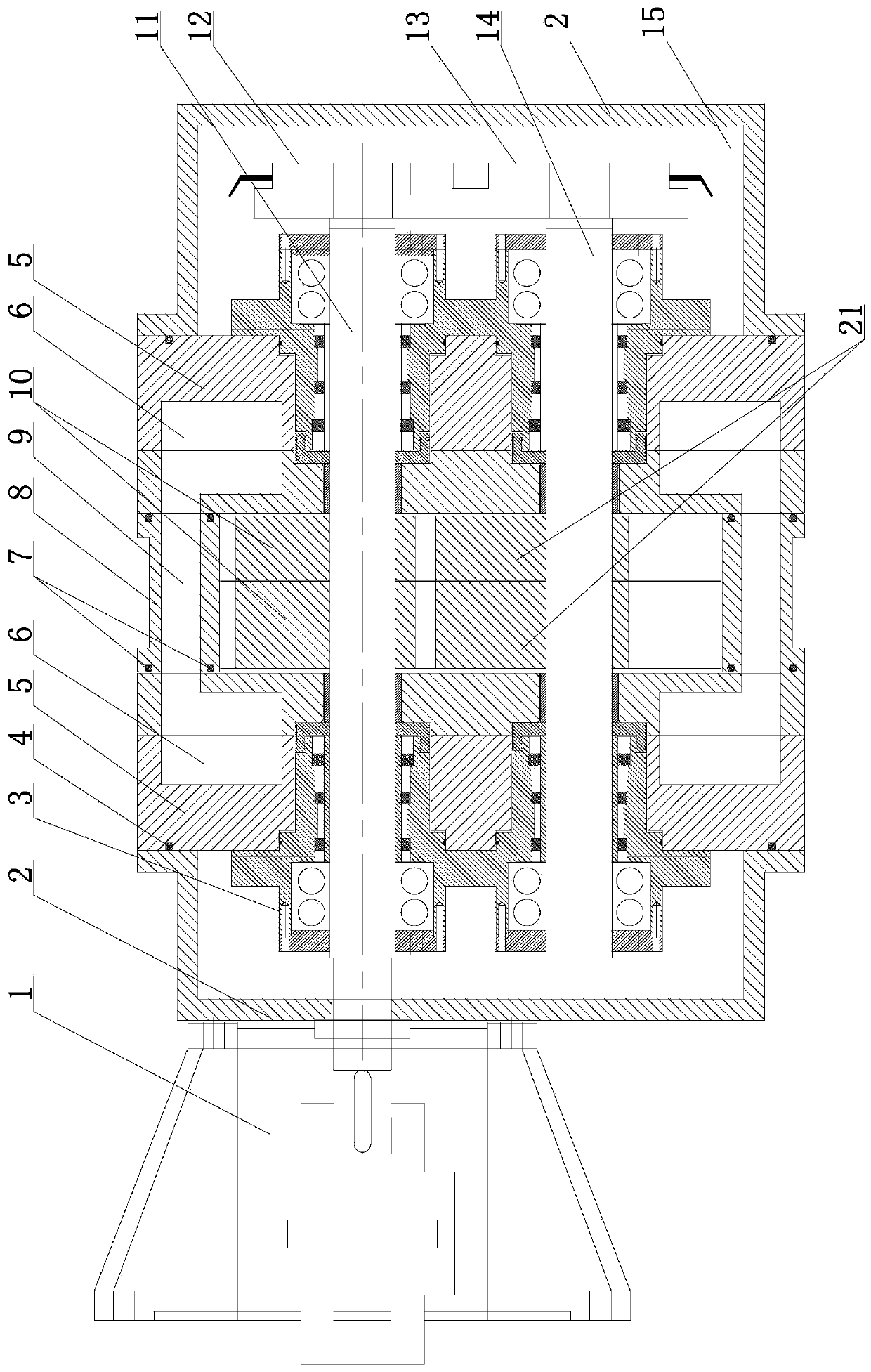
[0036] Such as Figure 1-9 As shown, the claw-type vacuum pump in this embodiment includes a pump body 8, a sealing plate 5 installed at the front and rear ends of the pump body 8, a pump cavity 19 formed by the pump body 8 and two sealing plates 5, and a pump cavity that runs through the pump cavity horizontally. 19 and the two rotor shafts located on the same horizontal plane and the two claw rotors with the same structure located in the pump chamber 19, the two rotor shafts realize synchronous reverse rotation through the gear transmission mechanism (that is, a pair of gears that mesh with each other and have the same number of modulus teeth). Rotate, the two claw rotors are respectively installed on the two rotor shafts and the two are engaged in conjugate engagement. An end cover 2 is respectively installed on the outer sides of the two sealing plates 5, and


PUM


Abstract

The invention belongs to the field of vacuum equipment, and particularly relates to a claw type vacuum pump. The claw type vacuum pump comprises a pump body, sealing plates at the two ends of the pumpbody, a pump cavity formed through the arrangement of the pump body and the two sealing plates in a surrounding manner, two rotor shafts which transversely penetrate through the pump cavity and are located on the same horizontal plane, and two claw type rotors positioned in the pump cavity; the two rotor shafts are synchronously and reversely rotated, and the two rotors are arranged on the two rotor shafts and are in conjugate engagement with the two rotor shafts; end covers are installed on the outer side of the sealing plates to form an oil tank; clearances of 0.20-0.25 mm are left betweenthe rotors and the sealing plates on both sides; and a pump inlet and a pump outlet are formed in the upper end and the lower end of the pump body respectively and are opposite to the meshing parts ofthe two claw type rotors. According to the claw type vacuum pump, the rotors can be effectively prevented from being locked, the whole pump can easily deal with complex working conditions of dust, viscous substances, easy carbonization and easy coking, and normal work is ensured; and the claw type vacuum pump can be used as vacuum obtaining equipment, can also be used for conveying gas, viscous liquid and the like, and has various functions.

Description


Claims


Application Information

Patent Timeline
Owner ZIBO ZEYI VACUUM EQUIP
Why Eureka
Try Eureka