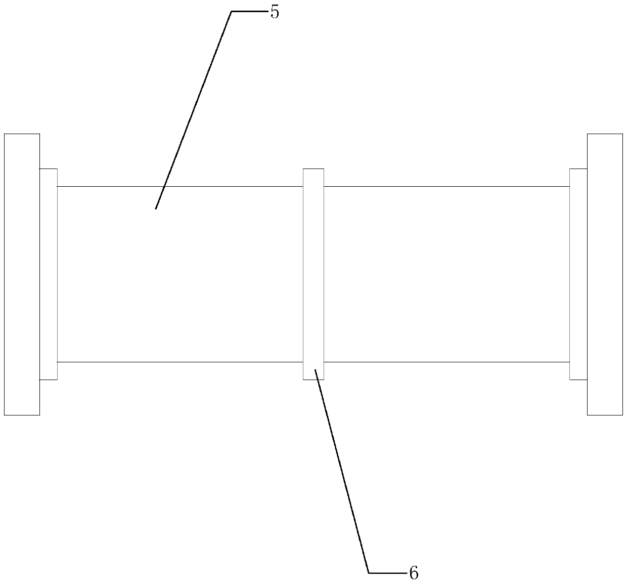
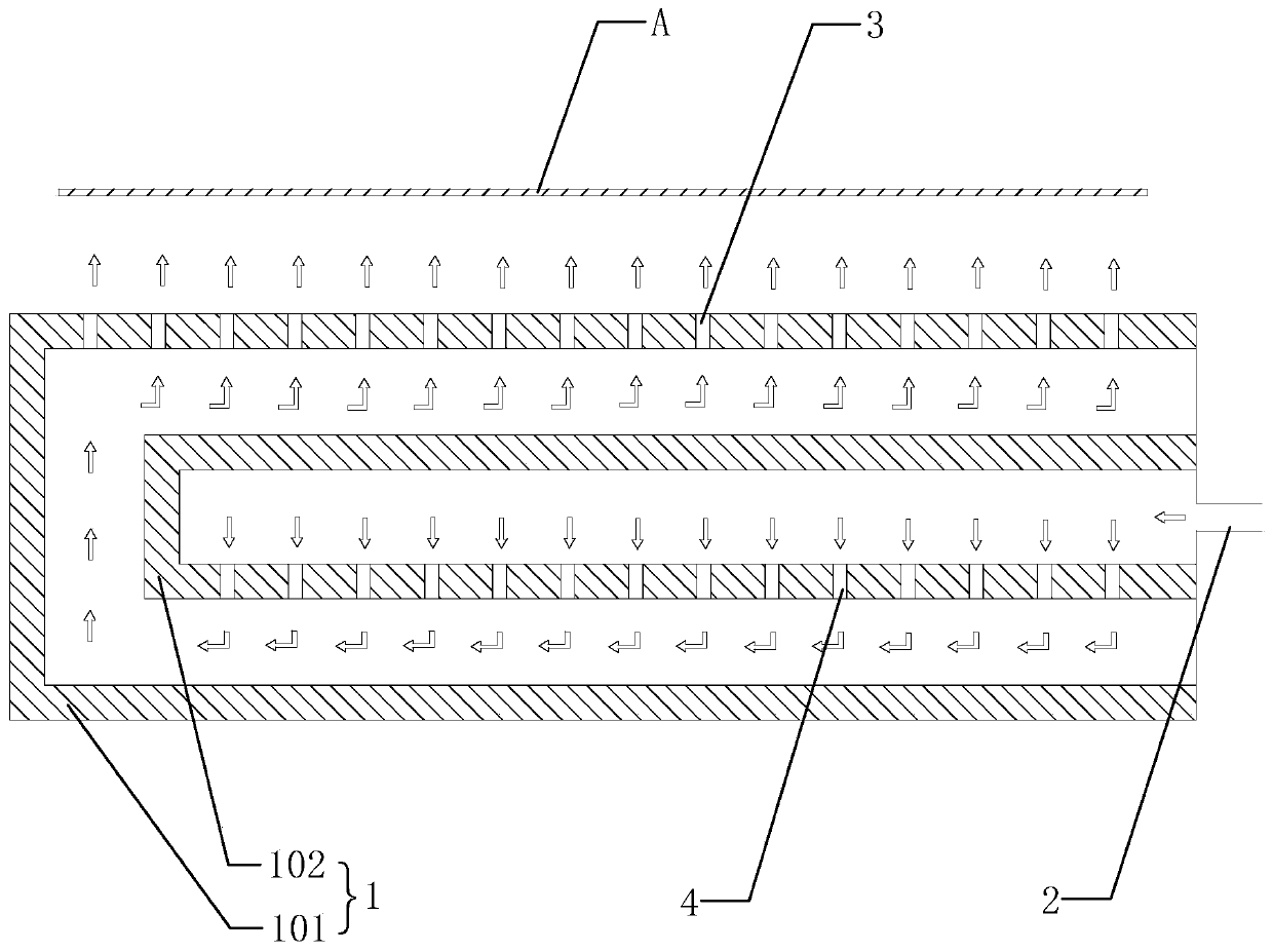
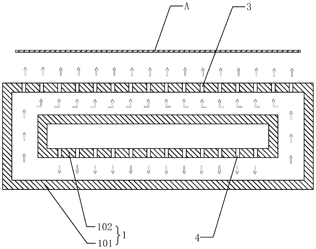
Liquid floating spray tray for COF wet process

A wet process and liquid flotation technology, applied in the field of COF processing, can solve the problems of dry film or line adverse effects, dry film scratches, line damage, etc., to improve the quality of COF products, avoid pollution or damage, and have a simple structure.

Pending Publication Date: 2019-07-12
江苏上达半导体有限公司
View PDF0 Cites 0 Cited by
  • Summary
  • Abstract
  • Description
  • Claims
  • Application Information

AI Technical Summary

Problems solved by technology

[0004] However, because the dry film of COF products is very thin and the lines are dense and slender, once it comes into contact with other objects, it is easy to cause scratches on the dry film or damage to the lines. Contact with the processing area of ​​the COF product itself during the process, or the developer crystallizes in the groove and contacts the processing area of ​​the COF product itse

Method used


Image

  • Liquid floating spray tray for COF wet process
  • Liquid floating spray tray for COF wet process
  • Liquid floating spray tray for COF wet process

Examples


Embodiment Construction

[0023] The idea, specific structure and technical effects of the present invention will be clearly and completely described below in conjunction with the embodiments and accompanying drawings, so as to fully understand the purpose, scheme and effect of the present invention. It should be noted that, in the case of no conflict, the embodiments in the present application and the features in the embodiments can be combined with each other.

[0024] It should be noted that, unless otherwise specified, when a feature is called "fixed" or "connected" to another feature, it can be directly fixed and connected to another feature, or indirectly fixed and connected to another feature. on a feature. In addition, descriptions such as up, down, left, and right used in the present invention are only relative to the mutual positional relationship of the components of the present invention in the drawings, unless otherwise specified.

[0025] Also, unless defined otherwise, all technical and sc


PUM

PropertyMeasurementUnit
Diameteraaaaaaaaaa

Abstract

The invention relates to a liquid floating spray tray for a COF wet process. The liquid floating spray tray comprises a sealed cavity, the side wall of the sealed cavity is provided with a water inletand a water outlet hole, and a developing solution enters the sealed cavity through the water inlet and is flushed out in a liquid column node through the water outlet hole to jack a COF product located at the upper portion of the water outlet hole and perform developing effect on the COF product. In the structure mentioned above, the liquid column formed by the developing liquid is configured todirectly support the COF product with no need for other structures to be in contact with the COF product for support so as to avoid usage of a traditional segment gap roller and so as not to need theside design for the segment gap roller, and the structure is simple; and moreover, it is avoided that the structure having a support effect is in contact with the COF product to pollute or damage a dry film or a circuit of the COF product so as to improve the COF product quality.

Description


Claims


Application Information

Patent Timeline
Owner 江苏上达半导体有限公司
Why Eureka
Try Eureka