Thermal shoe

A technology for warm shoes and shoe barrels, applied in the field of warm shoes, can solve the problems of overheating or overcooling, surface heating, difficult heating temperature, etc., and achieve the effects of enhancing comfort, enhancing sealing, and enhancing connection strength

Active Publication Date: 2019-07-30
WENZHOU POLYTECHNIC
View PDF9 Cites 0 Cited by
  • Summary
  • Abstract
  • Description
  • Claims
  • Application Information

AI Technical Summary

Benefits of technology

This patented technology uses an electric heater or other means for creating steam from hot liquid (water) at high temperatures. When this process starts after activation, tiny droplets are released onto surfaces like clothes during washing cycles. These small particles help keep them dry while they don't get dirty quickly enough when worn again later on. To prevent these contaminants from getting stuck with shoes made of rubber materials used for walking purposes, there should have some moisture added beforehand. A special flap called a clothespin helps make sure no harmful substances enter the footwear storage area where dirt gets collected.

Problems solved by technology

This technical problem addressed by this patented technology relates to improving energy utilization for electricity generating devices (ESPs) that generate electrical current when exposed to an alternating voltage signal from outside sources such as solar cells or wind turbines without adding too much weight or making them bulky due to their complicated construction with multiple components like wires and insulators.

Method used


Image

  • Thermal shoe
  • Thermal shoe
  • Thermal shoe

Examples


Embodiment Construction

[0029] The present invention will be further described with reference to the accompanying drawings.

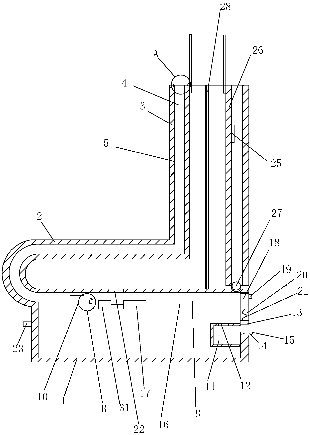
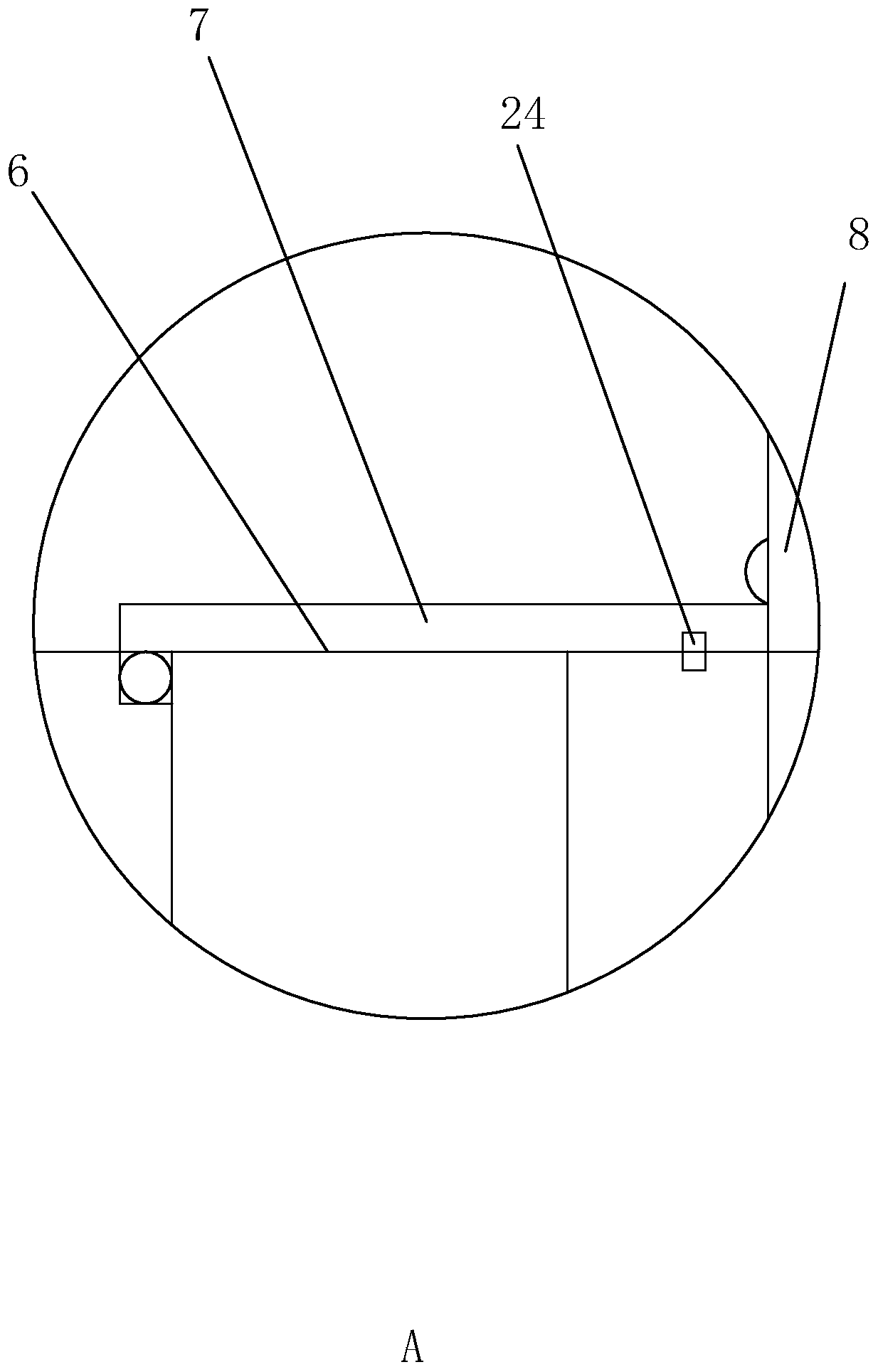
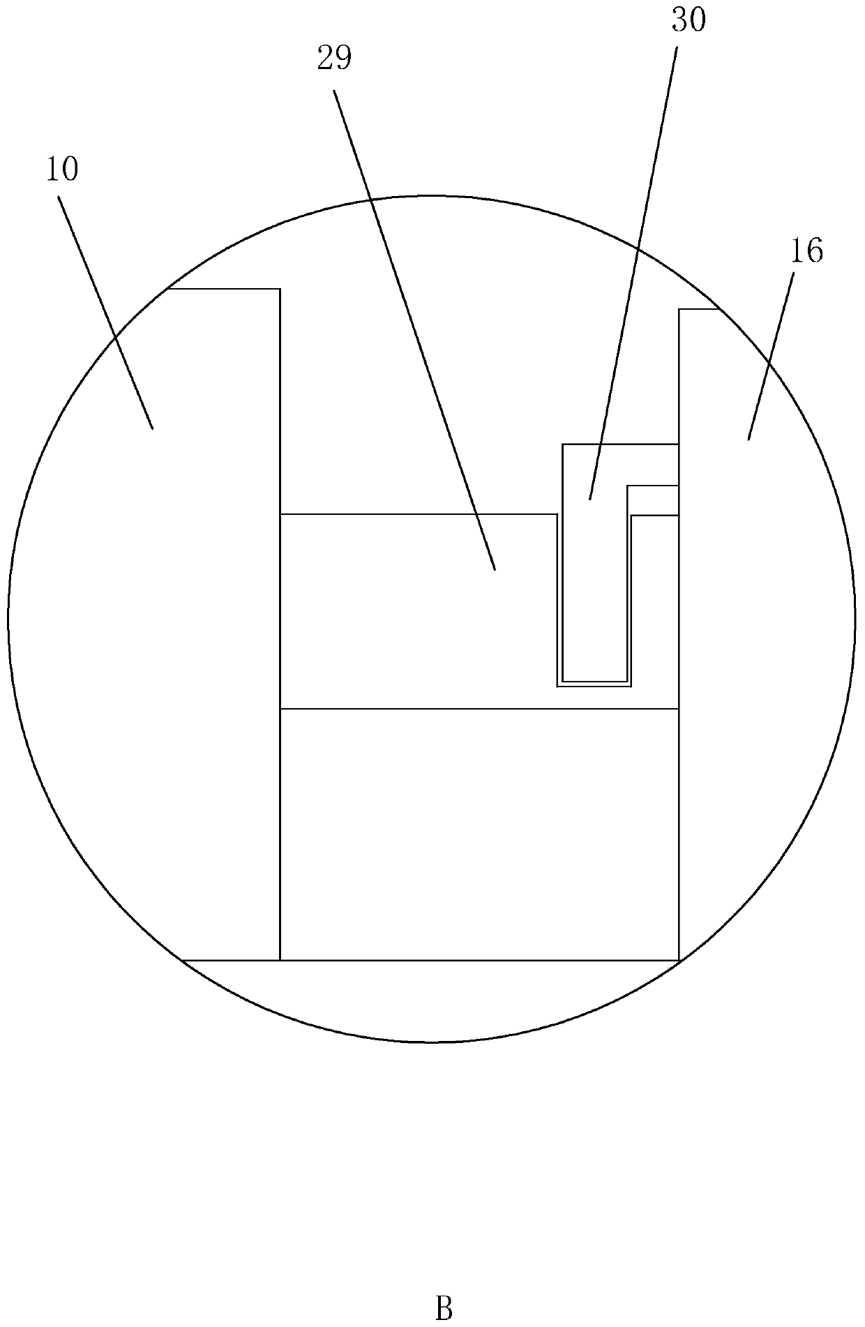
[0030] a warm shoe such as figure 1 , figure 2 , image 3 and Figure 4 As shown, it includes a sole 1, a vamp 2 and a shoe barrel 3. A heating device is arranged inside the sole 1. The sole 1 and the shoe barrel 3 are jointly provided with the same circulation groove 4. The circulation groove 4 is located between the sole 1 and the shoe barrel. A built-in closed space is formed in the cylinder 3 . The tank wall of the circulation tank 4 is provided with a waterproof layer 5, and the waterproof layer 5 restricts the passage of water vapor. The top of the shoe barrel 3 is provided with an exhaust groove 6 communicating with the circulation groove 4, and the notch of the exhaust groove 6 is provided with a grid block 7, and the grid block 7 can limit the communication between the exhaust groove 6 and the outside world. The shoe barrel 3 is integrally connected with a protecti


PUM


Abstract

The invention relates to a thermal shoe. The thermal shoe comprises a sole, a vamp, a shoe tube, a heating device, a circulation groove, a waterproof layer, an exhaust groove, a blocking sheet, a protective soft board, a groove, a micro cylinder, a water storage tank, a gas permeable membrane, a water injection tank, a bucket and a first magnetic block, wherein when the bucket closes an opening ofthe water injection tank, the bucket and the sole are squeezed; after the heating device is started, water in a water outlet groove is heated to be evaporated to form water vapor passing through thegas permeable membrane and entering the circulation groove, since the specific heat capacity of the water is larger, a warm state can be maintained for a long time, and since the water vapor increases, the gas pressure can increase to jack up the blocking sheet, therefore the water vapor escapes from the shoe tube; the water in the water outlet groove needs to be supplemented regularly, the bucketis rotated, thereby putting the water into space formed by the bucket, then the bucket is rotated to transfer the water into the water injection tank; the first magnetic block can enhance the connection strength between the bucket and the sole and enhance the sealing property.

Description


Claims


Application Information

Patent Timeline
Owner WENZHOU POLYTECHNIC
Why Eureka
Try Eureka