Ammonia gas supply device

A supply device and ammonia gas technology, applied in the direction of gas/liquid distribution and storage, fixed catheter components, pipeline systems, etc., can solve the problems of increasing the water content of ammonia gas, unstable ammonia gas supply, reducing ammonia gas concentration, etc., to achieve Reduce risks, save production time and costs, and achieve high-quality output effects

Pending Publication Date: 2019-08-02
KAISTAR LIGHTING (XIAMEN) CO LTD +1
View PDF5 Cites 0 Cited by
  • Summary
  • Abstract
  • Description
  • Claims
  • Application Information

AI Technical Summary

Benefits of technology

The technical effect of this inventor's design is that its equipment does not require constant maintenance or replacing pipes when used for producing ammonium nitrate solution (AN). It connects directly from one part called the apparatus itself instead of relying solely upon another component like a separate supplier system. This reduces costs while still ensuring good-quality product is produced at all times during operation. Additionally, by utilizing both thermal energy generated through direct contact between water and NH3, the process becomes more efficient than traditional methods due to less wasted materials compared to other systems such as urea decomposition method.

Problems solved by technology

Technological Problem: Current methods for producing high-purity nitrogen involve generating large amounts of wasted ammonium hydroxide solution with other chemicals like sulfur dioxide, methane, etc., along with unwanted impurities such as oxygen, carbon monoxyde, carbonyl compounds, metal salts, organics, heavy metals, bacterial spores, viruses, dirt particles, silica gel residue, iron oxides, calcium salt, magnesite, chlorine ion, phosphorus, boron, arsenic, selenium, tellurian mines, mineral deposits, plasma generators, and others involved in various industries due to their potential negative effects on environment health caused by harmful emissions associated therewith.

Method used


Image

  • Ammonia gas supply device
  • Ammonia gas supply device
  • Ammonia gas supply device

Examples


Embodiment Construction

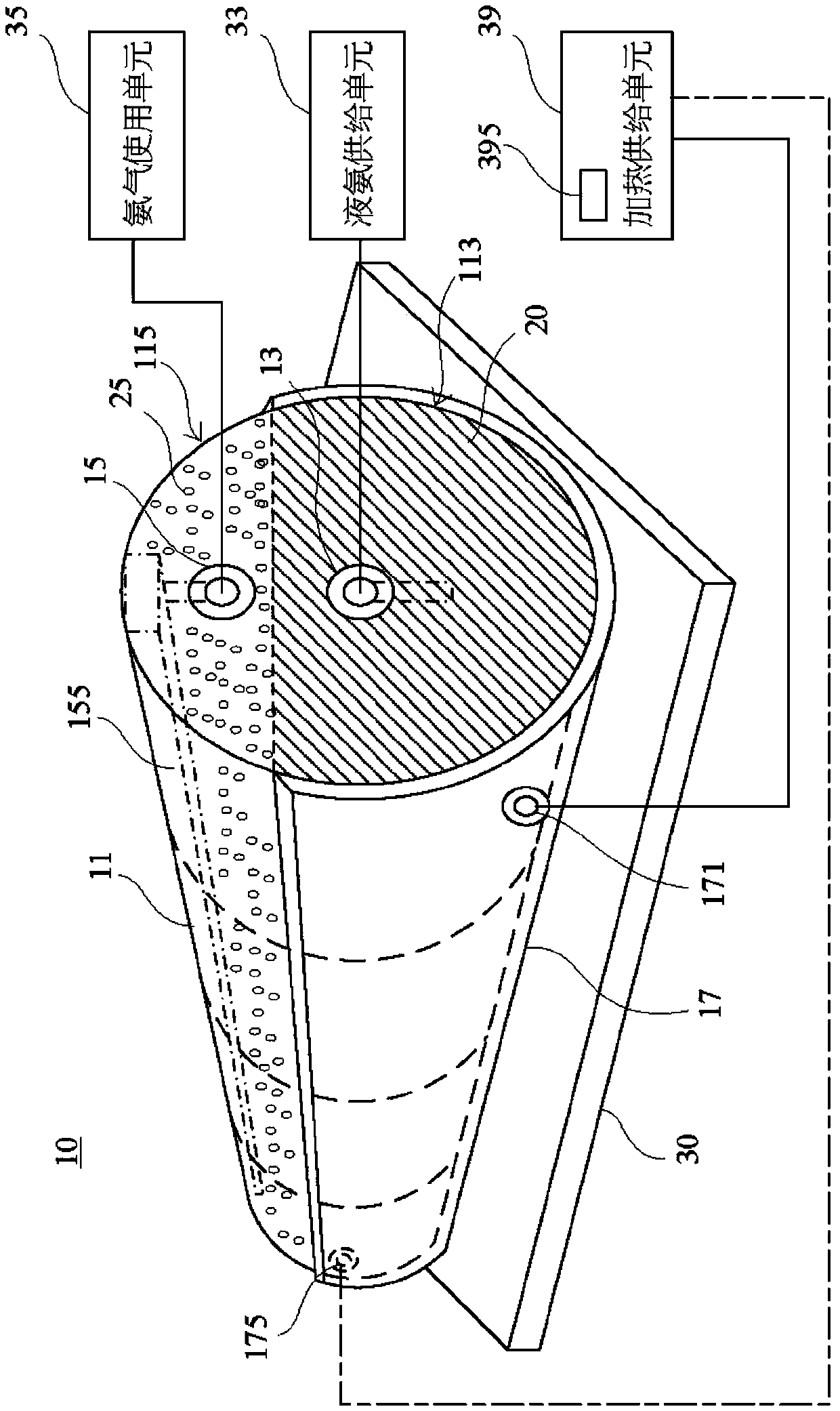
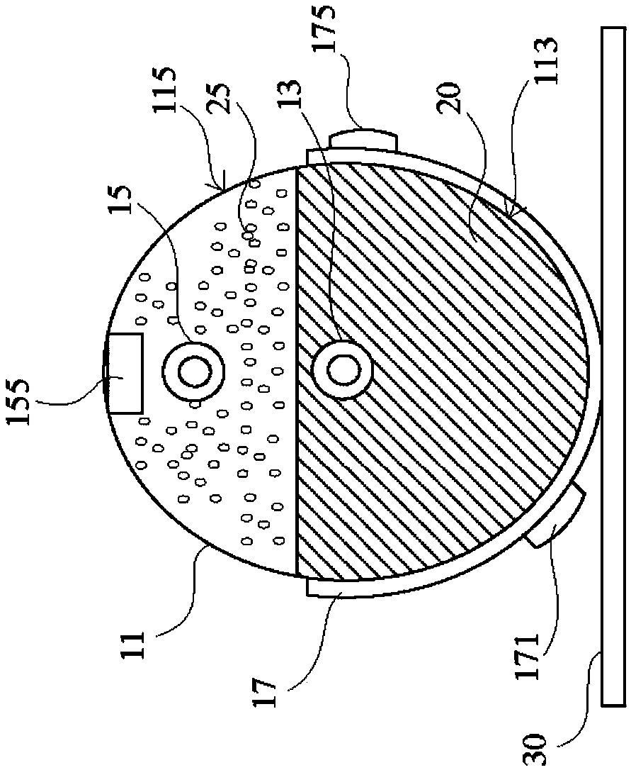
[0033] First, see figure 1 and figure 2 , are a schematic structural diagram and a side view of an embodiment of the ammonia gas supply device of the present invention, respectively. As shown in the figure, the ammonia gas supply device 10 of the present invention is mainly a fixed storage tank 11, such as but not limited to a fixed storage tank 11 that can be fixed on a plant substrate 30. The fixed storage tank 11 can be used for A liquid ammonia 20 is stored, and one side of the fixed storage tank 11 is provided with a liquid ammonia inlet and outlet piece 13 and an ammonia gas output piece 15 . The liquid ammonia inlet and outlet member 13 can be connected to a liquid ammonia supply unit 33, such as but not limited to a liquid ammonia supply unit 33 in the same workshop as the workshop substrate 30, which can be adjusted according to the capacity of the liquid ammonia 20 in the fixed storage tank 11. The liquid ammonia 20 is replenished in a timely manner into the fixed st


PUM


Abstract

The invention relates to an ammonia gas supply device. The ammonia gas supply device comprises a fixed storage tank for storing liquid ammonia, a heating covering sleeve and a cooling covering sleeve.The heating covering sleeve covers the outer surface of a lower half tank body of the fixed storage tank, the cooling covering sleeve covers the outer surface of an upper half tank body of the fixedstorage tank, and a liquid ammonia inflow and outflow part and an ammonia gas output part are arranged on one side edge of the fixed storage tank. The liquid ammonia inflow and outflow part can be externally connected with a liquid ammonia supply unit, and conveys the liquid ammonia into the fixed storage tank. The heating covering sleeve is connected with a heating supply unit, and introduces heating fluid, the liquid ammonia stored in the fixed storage tank is gently heated through the heating fluid flowing through the heating covering sleeve, and ammonia gas stably generated after heating can rise to the top end of the fixed storage tank and be conveyed to an ammonia gas use unit through an ammonia gas collecting pipe arranged at the top end of the fixed storage tank and the ammonia gasoutput part. The use safety of the ammonia gas can be improved, and the production cost of the ammonia gas and the influences on environments can be reduced.

Description


Claims


Application Information

Patent Timeline
Owner KAISTAR LIGHTING (XIAMEN) CO LTD
Why Eureka
Try Eureka