Automatic steel bar bundling position identification method

An identification method and steel bar technology, applied in the field of steel bar binding, can solve the problems of high cost of safety facilities, large personal safety hazards, and quality hidden dangers, and achieve the effect of avoiding safety hazards and high costs

Active Publication Date: 2019-08-06
ZHEJIANG UNIVERSITY OF SCIENCE AND TECHNOLOGY
View PDF15 Cites 10 Cited by
  • Summary
  • Abstract
  • Description
  • Claims
  • Application Information

AI Technical Summary

Benefits of technology

This technology helps prevent errors when attaching reinforcement bars during construction or maintenance work on buildings. It uses an automated system for identifying which parts are needed at each end of the bar before it's being attached. By transmitting location data from one part to another without requiring manual labor, these systems help reduce safety hazards associated with manually handling heavy loads while ensuring better results.

Problems solved by technology

This patents discusses various methods used during the installation phase of steel binder (stirring) between columns and horizontal joists. These techniques include connecting diagonal lines through weld rods, attaching anchor plates around circular rings, creating diagonal connections within the framework, adding loadings along the edges of these diagonal paths, applying tensional force to connect the legs together, arranging cross members across the frame's corners, joining backrest steels, and bonding struts onto the top surface of the tower shelf. However, this technique requires skilled laborers who can safely perform it while also ensuring proper placements and avoiding potential health risks associated with manual operations.

Method used


Image

  • Automatic steel bar bundling position identification method
  • Automatic steel bar bundling position identification method
  • Automatic steel bar bundling position identification method

Examples


Embodiment Construction

[0051] In order to illustrate the embodiments of the present invention more clearly, the specific implementation manners of the present invention will be described below with reference to the accompanying drawings. Obviously, the accompanying drawings in the following description are only some embodiments of the present invention, and those skilled in the art can obtain other accompanying drawings based on these drawings and obtain other implementations.

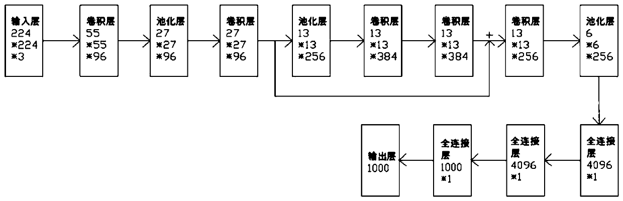
[0052] The automatic steel bar binding position recognition method of the embodiment of the present invention is applied to a system framework including a computer and a network camera. Specifically, the computer vision-based automatic steel bar binding position recognition method includes the following steps:

[0053] S1. Preprocess the positive sample pictures with steel bar binding objects and the negative sample pictures without steel bar binding objects respectively, and then generate a sample model by training the classifi


PUM


Abstract

The invention relates to an automatic steel bar bundling position identification method which comprises the steps that a positive sample picture with a steel bar bundling object and a negative samplepicture without a steel bar bundling object are preprocessed respectively, then a sample model is generated through a training classifier, and the sample model is used for recognizing steel bars and stirrups needing to be bundled in a designated focal plane; a real-time picture of a to-be-bundled area is acquired, the real-time picture is preprocesed, and thenutilizing the sample model is used toidentify steel bars and stirrups in the preprocessed real-time picture; after the ROI area is selected, Hough straight line detection is conducted to obtain the slope of the steel bars and the stirrups, and the intersection points of the steel bars and the stirrups are calculated to obtain the coordinates of the intersection points of the steel bars and the stirrups. The position, needing to be bundled, of the steel bar can be intelligently recognized, and therefore data of the corresponding position can be transmitted to the lower computer, and the steel bar bundling operation can be conveniently carried out through the lower computer; not only can the bundling task be completed with high quality, but also potential safety hazards and high cost of manual operation can be effectively avoided.

Description


Claims


Application Information

Patent Timeline
Owner ZHEJIANG UNIVERSITY OF SCIENCE AND TECHNOLOGY
Why Eureka
Try Eureka