USBC cable testing circuit

A cable testing and circuit technology, which is applied in the field of USBC cable testing circuits, can solve problems such as product hidden dangers, open circuits, short circuits, etc., and achieve the effect of accurate testing and high accuracy

Active Publication Date: 2019-08-13
BIZLINK ELECTRONICS KUNSHAN CO LTD
View PDF11 Cites 2 Cited by
  • Summary
  • Abstract
  • Description
  • Claims
  • Application Information

AI Technical Summary

Problems solved by technology

[0002] When testing the USBC cable, a multimeter is usually used to detect the welding status of the USB-C on the PCBA. The distance between the electrical pins of the USB-C terminal is very clos

Method used


Image

  • USBC cable testing circuit
  • USBC cable testing circuit
  • USBC cable testing circuit

Examples


Embodiment Construction

[0015] The present invention will be further described below in conjunction with the embodiments shown in the accompanying drawings.

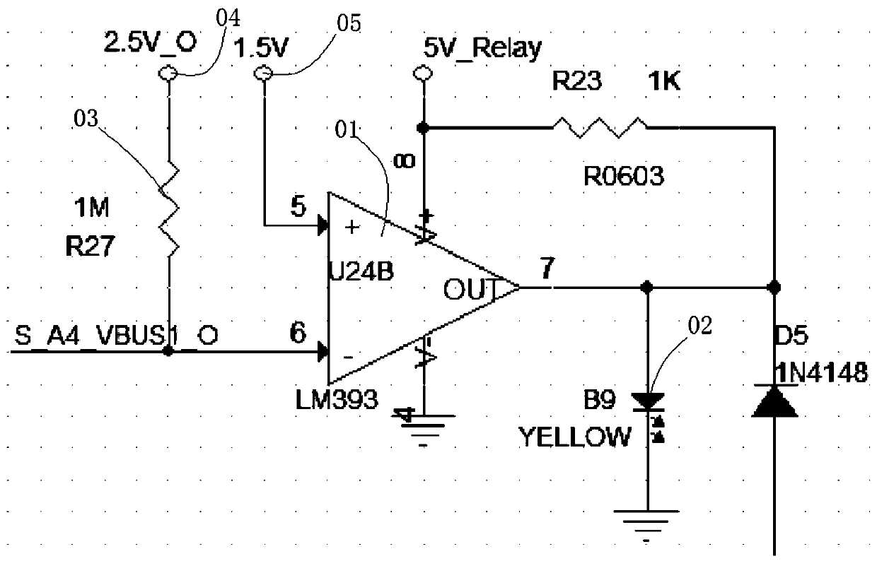
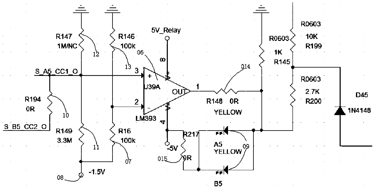
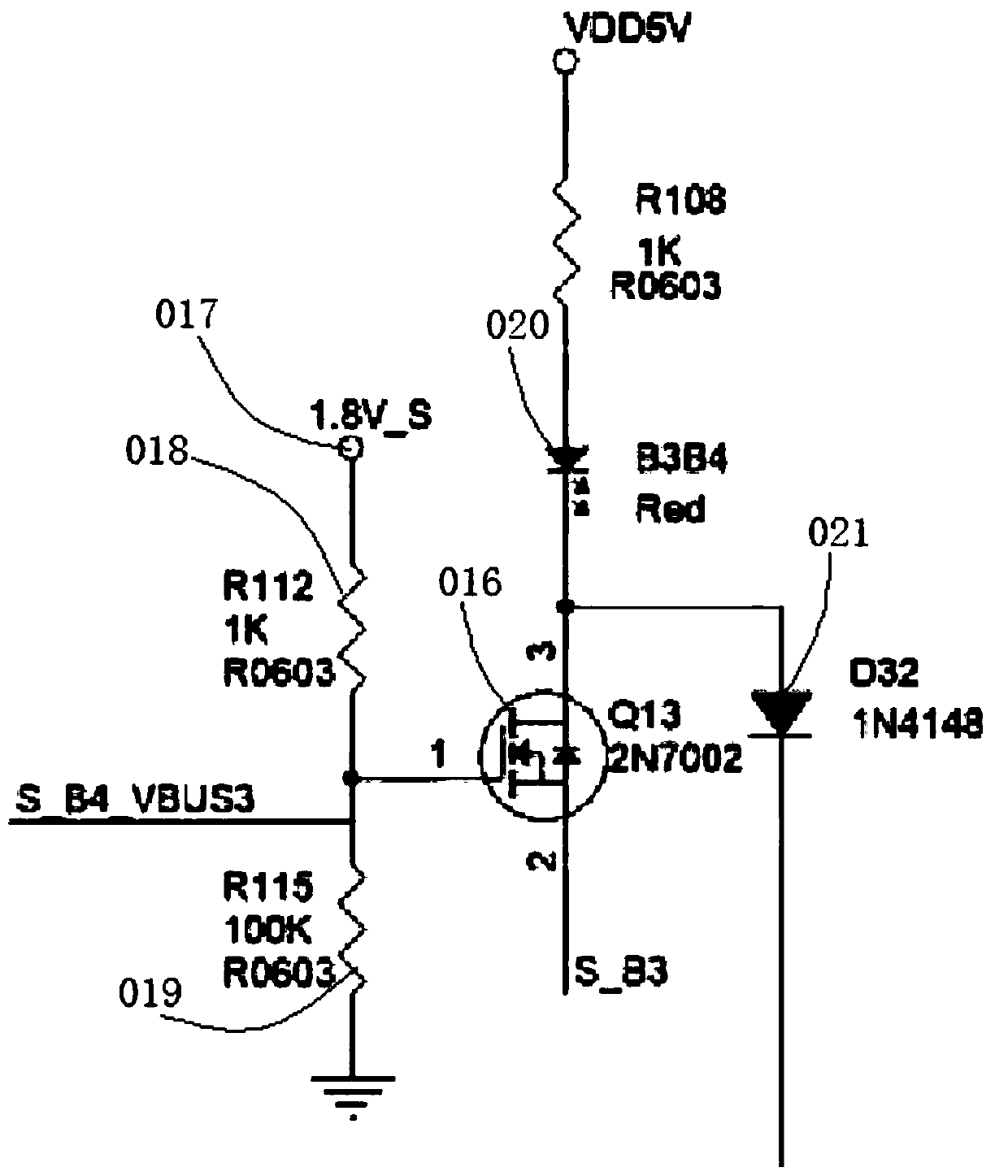
[0016] Such as figure 1 Shown, the USBC cable test circuit, it includes several positive voltage modules for testing the positive voltage of the USBC connector open circuit and negative voltage modules for testing the negative voltage and several short circuit test modules for testing the short circuit test of the USBC connector, the USBC cable The 24 pins take two adjacent pins as a group to form 22 sets of pin pairs, and the two pin pairs opposite to the front and back of the USBC form a pin pair group. The positive voltage module is used to test the connection to a low-impedance pin pair, the negative voltage module is used to test a high-impedance pin pair;

[0017] Each positive voltage module 41 includes a first comparator 01, an indicator light 02 connected to the output terminal of the first comparator, and a first power supply connected


PUM


Abstract

The present invention discloses a USBC cable testing circuit, comprising a plurality of positive voltage modules for a USBC connector open test positive voltage, a plurality of negative voltage modules for testing a negative voltage and a plurality of short circuit test modules for testing a USBC connector short circuit test. 24 pins of a USBC cable form 22 pin pairs with two adjacent pins as a pair. Two pin pairs of front and back of the USBC form a pin pair group, the positive voltage module is used to test a pin pair that is connected to a low impedance, and the negative voltage module is used to test a pin pair that is connected to a high impedance. The test circuit has following advantages: time saving, wherein measurement of 24 pin positions of the USB-C is completed in a few seconds, and measurement for the prior art needs 10 minutes; trouble saving, wherein a test fixture can finish measuring the USB-C terminal while the prior art requires many devices such as a multimeter anda microscope. The testing circuit has high accuracy, has the small USBC connector, and a close distance between each pins. Only with the method, accurate testing can be achieved.

Description


Claims


Application Information

Patent Timeline
Owner BIZLINK ELECTRONICS KUNSHAN CO LTD
Why Eureka
Try Eureka